APPLICATION NOTE LA05-0020
General Sensing Application Note LA05-0020
Copyright © 2013 Lion Precision. www.lionprecision.com
Summary:
Vibration is a complex measurement containing many different parameters. Different measurement technologies have advantages and disadvantages depending on the ultimate vibration measurement goals. This Application Note addresses all of these areas.
Vibration Measurement
Vibration is a time-based (periodic/cyclic) displacement of an object around a center static position. The following contributing factors have a complex relationship with the magnitude and rate of the vibration:
- The object’s own natural frequencies and stiffness
- The amplitude and frequencies of any external energy source(s) inducing the vibration
- The coupling mechanism between vibration energy source and the object of interest.
Vibration measurement is complex because of its many components – displacement, velocity, acceleration, and frequencies. Also, each of these components can be measured in different ways – peak-to-peak, peak, average, RMS; each of which can be measured in the time domain (real-time, instantaneous measurements with an oscilloscope or data acquisition system) or frequency domain (vibration magnitude at different frequencies across a frequency spectrum), or just a single number for “total vibration.”
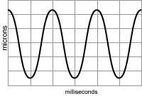 Viewing vibration in the time domain reveals the instantaneous location of the vibrating surface at different moments in time. |
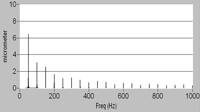 Viewing vibration in the frequency domain reveals the magnitude of vibration at different frequencies. |
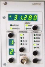 “Total Vibration” can be displayed with the TIR function on the MM190 Meter Module. |
Vibration measurement is sometimes used as an indirect measurement of some other value. The final measurement goal determines the approach to the measuring vibration. Often, condition monitoring– predicting or monitoring wear, fatigue, and failure – requires vibration measurements meant to determine the kinetic energy and forces acting upon an object . This is often called inertial vibration. Monitoring machinery motors (especially the bearings) in critical applications is an example. In these cases, the measurement of acceleration provides an easy conversion to units of force assuming the mass of the object is known.
Other applications are concerned with the displacement of the object of interest because unintended displacements degrade performance of a system. Hard-disk drives and machine tools are examples of this type of vibration measurement, sometimes referred to as positional vibration or relative vibration.
Impulse and Continuous Vibration Measurement
Two more scenarios for vibration are continuous and impulse vibration measurements. Continuous vibration measurements are used for condition monitoring and operational testing. It directly measures what happens to the object of interest under real operating conditions.
An impulse vibration measurement involves striking the object, often with a “calibrated hammer” that measures impact force, and then measuring the resulting vibration of the object. This type of test reveals resonances within the object to help predict its behavior in operating conditions. It often leads to design considerations to either avoid or accentuate resonant frequencies depending on the application.
Vibration Measurement Equipment and Vibration Sensor Technology
Vibration is measured as an acceleration, velocity, or displacement. Each has advantages and disadvantages and each vibration measurement unit can be converted to the others although with potentially adverse consequences from the conversion. Acceleration and displacement are the most common methods of vibration measurement.
Measuring Vibration with Accelerometers
Accelerometers are small devices that are installed directly on the surface of (or within) the vibrating object. They contain a small mass which is suspended by flexible parts that operate like springs. When the accelerometer is moved, the small mass will deflect proportionally to the rate of acceleration. A variety of sensing techniques can be used to measure the amount of deflection of the mass. Because the mass and spring forces are known, the amount of deflection is readily converted to an acceleration value. Accelerometers can provide acceleration information in one or more axes.
Inertial vibration measurements in which the forces acting upon the object are the critical factor are well served by accelerometers, but accelerometers are sensitive to frequency. Vibrations at higher frequencies have greater accelerations than those at lower frequencies. For this reason, accelerometers produce very low signal levels for low-frequency vibration and can have poor signal to noise ratios. Also, using integration to derive velocity or double integration to derive displacement values reduces high-frequency signals.
Attaching accelerometers to the object of interest changes the mass of the object which changes its natural resonant frequencies. When the mass of the object is considerably larger than the mass of the accelerometer, as is often the case, the effect is negligible. But it does limit the use of accelerometers on smaller objects.
Accelerometers are a great choice for larger objects, vibrating at higher frequencies, in which the inertial forces acting upon the object is what needs to be measured.
Measuring Vibration with Noncontact Displacement Sensors
Capacitive noncontact displacement sensors
Noncontact displacement sensors mount with a small gap between the sensor (probe) and a surface of the vibrating object. Capacitive and eddy-current displacement sensors are best choices for high-resolution, high-speed measurements. Because their outputs are displacement measurements, they are perfect for relative vibration (positional vibration) measurements. These measurements are made when the physical location of the surface of the vibrating object at any moment in time is a critical factor.
With frequency response over 10 kHz and as high as 80 kHz, and resolutions as low as nanometers, these sensors indicate the precise instantaneous location of the object even when it is moving at high speed.
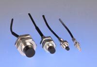
Eddy-current noncontact displacement sensors
Because the sensors are not mounted on the object, they do not change the object’s mass or its resonant characteristics. These sensors have a flat frequency response from DC to near their rated frequency response. Because the output is not affected by the frequency of the vibration, measurements are more accurate across the frequency spectrum.
Displacement data from these sensors can be differentiated to provide velocity information and differentiated a second time to obtain acceleration information. The differentiation process will limit low frequency signals and emphasize higher frequency signals. This will result in lower signal-to-noise ratios in the higher frequencies.
Instantaneous and Total Vibration
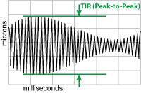
“Total Vibration” can be measured with TIR (peak-to-peak) captures of the vibration signal.
Displacement sensors produce outputs that can be observed in real-time on an oscilloscope or with a data-acquisition system. This real-time, instantaneous data provides precise vibration data which can be used to determine a machine’s performance as a function of time or angular location of a rotating part.
In other applications, a simple “total vibration” number is required. To obtain such a number, the sensor output will need to be processed. If you are using Elite Series capacitive displacement sensors, the MM190 Signal Processing and Meter module can derive a total vibration measurement. The peak capture functions include a TIR (Total Indicator Reading) option which displays the difference between the most negative and most positive measurements. A Reset button clears those captured values so new values can be captured. This single peak-to-peak (peak-to-valley) measurement is an indication of total vibration.
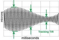
Changing “total vibration” can be measured with Tracking TIR option of the MM190 Module.
If the vibration value is expected to change over time, perhaps during an adjustment to the mechanical system, the Tracking TIR option can be used. Tracking TIR displays the peak-to-peak value, but the peak values are allowed to slowly decay toward zero. In this way, the indicator shows the current TIR value after a few seconds, even if the value has decreased. This function facilitates experimentation with the object’s environment to determine what may reduce total vibration without the necessity of manual resets of the peak values.
Displacement Sensor Probe Mounting
When measuring vibration, it is likely that the displacement sensors will also be exposed to a vibration. To minimize the effects of vibration on the sensors themselves, they must be rigidly mounted. Probes with threaded bodies tightened into a rigid mount should provide the rigidity needed to minimize vibration effects.
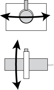 Set-screw mounting locks the probe along the probe’s axis, but there may still be movement in the other two axes, especially at the micro and nano levels. |
 A clamp mount is a more stable mount than a set-screw mount. But at the micro and nano levels, form errors can result in only a two-point clamp much like a set-screw mount. |
 A three-point clamp mount is inherently stable and not effected by small form errors in roundness. |
Smooth, cylindrical probes which are clamp mounted require careful consideration as they are more likely to be affected by a vibrating environment. There are different clamp mounting methods for cylindrical style probes; some are better than others. When measuring at high resolutions, mounting design begins to play an important role in measurement quality.
A common mounting method is a thru hole with a set screw to secure the probe. For measurements in a stable, non-vibrating environment not measuring at the sub-micron levels, this method is often sufficient. But this system only secures the probe at two points (the set screw and the point opposite the set screw) which allows it some freedom of motion in at least one axis. For high-resolution measurements in a vibrating environment, a better system is required.
A “pinch clamp” mount in which a thru hole is tightened on the cylindrical probe is a better solution. The full circumference clamp engages more of the surface of the probe and will provide a more stable mount. However, any out-of-roundness of the probe or the thru-hole can begin to function like the two point clamp of a set screw.
The most stable clamping method uses a pinch clamp that clamps the probe at three or four points rather than the full circumference. This method remains stable in spite of roundness errors of the probe body or the clamp’s thru-hole.
Additional Capacitive Displacement Sensor Mounting Considerations
Capacitive displacement sensors have a measurement “spot size” about 130% of the diameter of the sensing area of the probe. If the measurement target area is smaller than this it will be susceptible to errors and may require special calibration.
Multiple Capacitive Probes
When multiple capacitive probes are used with the same target, their drive electronics must be synchronized. Lion Precision multi-channel capacitive sensor systems (Elite Series and CPL230) use synchronized electronics. Capacitive sensors require no minimum distance between adjacent probes.
Environmental Considerations for Capacitive Sensors
Capacitive sensors require a clean, dry environment. Any change in the material between the probe and target will affect the measurement.
All sensors have some sensitivity to temperature, but Lion Precision capacitive sensor systems are compensated for temperature changes between 20°C and 35°C with a drift of less than 0.04%F.S./°C.
Ordinary changes in humidity have no effect on capacitive displacement measurements. Humidities into the 90% range can begin to affect the measurement; any condensation in the measurement area will render the measurement invalid.
Additional Eddy-Current Displacement Sensor Mounting Considerations
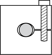
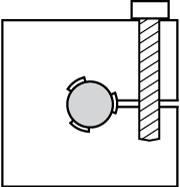
![]() Eddy-Current displacement sensors use a magnetic field that engulfs the end of the probe. As a result, the “spot-size” of eddy-current displacement sensors is about 300% of the probe diameter. This means any metallic objects within three probe diameters from the probe will affect the sensor output.
Eddy-Current displacement sensors use a magnetic field that engulfs the end of the probe. As a result, the “spot-size” of eddy-current displacement sensors is about 300% of the probe diameter. This means any metallic objects within three probe diameters from the probe will affect the sensor output.
This magnetic field also extends along the probe’s axis toward the rear of the probe. For this reason, the distance between the sensing face of the probe and the mounting system must be at least 1.5 times the probe diameter. Eddy-Current displacement sensors cannot be mounted flush with the mounting surface unless a properly designed counter bore exists around the probe.
Eddy-current probe mounting must allow a metal-free space around the tip at least three times the probe diameter. Flush mounting requires a counter bore.
If interfering objects near the probe is unavoidable, a special calibration, ideally done with the probe in the fixture, will have to be performed.
Multiple Eddy-Current Probes
When multiple probes are used with the same target, they must be separated by at least three probe diameters to prevent interference between channels. If this is unavoidable, special factory calibrations are possible to minimize interference.
Environmental Considerations for Eddy-Current Sensors
Linear displacement measurements with eddy-current sensors are immune to foreign material in the measurement area. The great advantage of eddy-current non-contact sensors is that they can be used in rather hostile environments. All non-conductive materials are invisible to eddy-current sensors. Even metallic materials like chips from a machining process are too small to interact significantly with the sensors.
Eddy-Current sensors have some sensitivity to temperature, but the systems are compensated for temperature changes between 15°C and 65°C with a drift of less than 0.01%F.S./°C.
Changes in humidity have no effect on eddy-current displacement measurements.