Capacitive Sensor TechNote LT03-0033
Copyright © 2012 Lion Precision. www.lionprecision.com
Summary
A rotating spindle generates error motions at many different frequencies. Those frequencies are determined by rotational speed, bearing component shape errors, external influences and other sources. Examination of these frequencies reveals that a 15 kHz bandwidth is sufficient to accurately measure high-speed spindles.
Spindle Motions
A noncontact sensor measures error motions of a rotating spindle in one axis. The frequency of motion in that axis determines the sensors needed bandwidth.
Spindle error measurements are usually made with sensors in multiple axes. To understand how those measurements are made, consider just one of those sensors. A single noncontact sensor measures displacements of a rotating target in one axis as the target moves toward and away from the sensor.
The bandwidth of the measurement system must be capable of measuring the frequency of motion of the spindle in that axis. Even for very high-speed spindles, these frequencies are usually well within a measurement systems capabilities.
Bandwidth of Sensors
With a 15 kHz bandwidth, sensor output is reduced to 70% at 15 kHz. Frequency response is flat until about 10 kHz.
Lion Precision CPL190 and CPL290 capacitive sensors are “flat” to about 10 kHz, meaning that measurements of targets moving at 10 kHz are accurate.
While they are flat to 10 kHz, the “bandwidth” is 15 kHz. It is critical to understand that the bandwidth specification of any sensor is the frequency at which the output voltage is reduced to 70.7% (-3dB) of lower frequency (or DC) output levels. This means that a target moving at 15 kHz with a displacement of 10 µm will only be measured as 7 µm.
The Fundamental Frequency
Due to eccentricity, all rotating targets will exhibit one cycle of error motion per revolution. This establishes a “fundamental frequency” and it is always:
Fundamental Frequency (in Hz) = RPM/60
A sensor that has a flat frequency response to 10 kHz can accurately measure fundamental motions of targets at speeds up to 600,000 RPM. A standard 15 kHz bandwidth sensor can reliably and repeatedly measure rotational speeds of 900,000 RPM although at 70% of actual amplitude.
Nonfundamental Frequencies
The frequency of all other error motions can be measured relative to the fundamental frequency. For example, a frequency that is twice as high as the fundamental frequency is simply labeled as “2.” This permits discussions of a general case rather than resorting to examples at specific frequencies that may not be relevant to an individual case.
Frequencies other than the fundamental frequency are also present in the error motions of a spindle. Imperfections in bearing components, mounts, motors, drives, structural vibration, and other factors each contribute a unique frequency. These error motions occur at integer and noninteger multiples of the fundamental frequency.
Synchronous Error Motions
Typical frequency distribution of synchronous error motions. Synchronous error motions occur at integer multiples of the fundamental frequency.
Error motions which are integer multiples of the fundamental frequency are said to be “synchronous” as they repeat at the same angular location with each rotation of the spindle. Synchronous errors are the result of rotor and stator imperfections, mounting stresses, and other sources affecting the shape of the rotor or stator.
Stator and Rotor Shape Errors
Synchronous error motions create “lobed” patterns. Higher numbers of lobes require higher bandwidth for accurate measurement.
Stators and rotors are not perfectly round. These imperfections create additional frequencies in the spindle motion which are always synchronous with the fundamental frequency. Two- and three-lobe shapes are common out-of-roundness errors. These form errors create spindle motion frequencies two and three times higher than the fundamental frequency. See figures at right.
A three lobe error would be accurately recorded at speeds up to 200,000 RPM by a flat-to-10 kHz system.
Mounting Induced Errors
Mounting of the spindle can create stresses in the bearing structure resulting in slight deformities. These create synchronous error motions and are essentially the same as stator and rotor shape errors, but the shape errors are introduced by the mounting stresses. These errors can occur at the fundamental frequency or higher. Theoretically, each mounting fastener could add another lobe to the synchronous error motion.
Motor Pole Print-Thru
The magnetic poles in motors create a normal force on the motor’s rotor that is different at the poles than between the poles. This varying force cycles on every rotation. Depending on the stiffness of the spindle bearing, this changing force can appear as error motions in the spindle. This motion is synchronous with the fundamental frequency.
The number of poles in the drive motor determines the shape of the print-thru error. For example, an eight-pole motor creates an 8-lobe pattern and would be accurately measured at speeds up to 75,000 RPM by a flat-to-10 kHz system. A typical drive motor has 4, 6, or 8 poles. Large motors may have more poles, but due to their size they turn at much slower speeds keeping the error motion frequencies comparatively low.
Asynchronous Error Motions
Some error motions occur at frequencies that are non-integer multiples of the fundamental frequency. While these errors may have a repeating cycle, they do not repeat at the same angular location of spindle rotation; they are not synchronous with the fundamental frequency.
Structural Vibration
The machine structure itself will have natural resonant frequencies that can appear in the spindle motion. Because of the size and mass of the machine structure, these frequencies are usually low (10-30 Hz) and may or may not be synchronous with the fundamental frequency. Because of their low frequency, they are easily measured by the sensors.
Rolling-Element Bearings (Asynchronous Error)
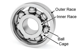
Each bearing component has a unique diameter which creates a unique frequency of error motion.
Rolling-element bearings have four basic components: the rolling element itself (ball or roller), the inner race, the outer race, and the cage. As the bearing turns, these elements interact mechanically; their inherent imperfections cause deviations in bearing forces and the axis of rotation which result in spindle error motions.
Each bearing component has its own shape errors which produce error motions in the spindle. The ratio of the diameters of the bearing components, as well as the contact angle of the rolling element, determine the relationships to the fundamental frequency. To prevent resonances within the spindle, bearings are intentionally selected so that these frequencies are not synchronous with the spindle rotor; therefore, these errors occur at non-integer multiples of the fundamental frequency.
Bearing Frequencies
Typical frequency distribution of asynchronous error motions occurring at “bearing frequencies.” Most of the distribution is below 4.5 times the fundamental frequency.
The frequency distribution at right shows where a typical ball-bearing’s bearing frequencies occur. The ball bearings turn on the inner race (ballpass) witha frequency just above 2 times the fundamental frequency. The cage frequency is a little less than half the fundamental frequency.
In the chart at right, harmonics occur at 4 ± the cage frequency, and the outer race is seen at just over 3. There is little activity above 4.5 times the fundamental frequency. Accurate measurements can be made of these error motions on spindles up to 130,000 RPM by a flat-to-10 kHz system.
The table below is another example of typical bearing frequencies shown as multiples of the fundamental frequency3. Here the highest frequency is 8.32. Accurate measurements can be made of these error motions on spindles up to 70,000 RPM by a flat-to-10 kHz system
| Number of Balls | Ball Diam. | Pitch Diam. |
BallPass Outer |
BallPass Inner |
Cage (FTF) |
Ball Spin |
| 15 | 0.312″ | 2.854″ | 6.68 | 8.32 | 0.45 | 4.52 |
Conclusion
While spindle speeds have increased dramatically over time, the error motion frequencies generated by the spindles are still within the measurement capabilities of Lion Precision sensor systems with 15 kHz bandwidth. The Spindle Error Analyzer is an effective and accurate tool when used with high-speed spindles.
References
1 – Precision Spindle Metrology, Eric R. Marsh, 2008, DesTech Publishing: Lancaster PA.
2 – Rolling Bearing Analysis, Tedric A. Harris, 1991, John Wiley & Sons: New York
3 – Bearing Frequencies, NTN Americas