USER’S GUIDE for the
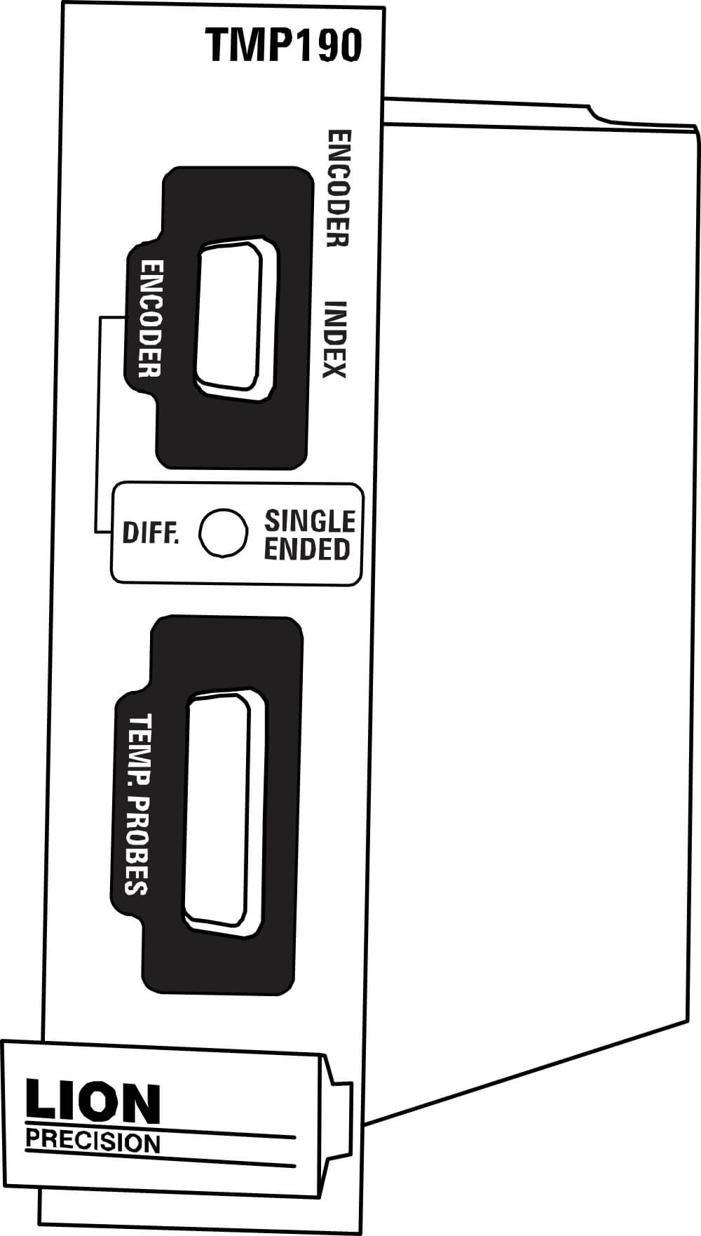
TMP190 – Temperature Sensing and Encoder/Index Input Module
TABLE OF CONTENTS
- Approvals and Safety Considerations
- Helpful Technical Support Documents Online
- TMP190 Temperature Sensing and Encoder/Index Input
- Elite Series Enclosures
- Accessories
Approvals and Safety Considerations
The Elite Series is compliant with the following CE standards:
Safety: EN 61010-1:2010
EMC: IEC 61326-1:2013, IEC 61326-2-3:2013
To maintain compliance with these standards, the following operating conditions must be maintained:
- All I/O connecting cables must be shielded and less than three meters in length
- AC power cables must be rated at a minimum of 250 V and 5 A
- AC power must be connected to a grounded mains outlet rated less than 20A
- Use the included CE approved power supply with 1-, 2-, and 3- slot enclosures. If an alternative power supply is used, it must have equivalent CE certification and provide safety isolation from the mains according to IEC60950 or 61010.
- Sensors must not be attached to parts operating at hazardous voltages in excess of 33VRMS or 70VDC
Use of the equipment in any other manner may impair its safety and EMI protections.
The sensing tips of capacitive probes produce voltages as high as 70 Vrms. These are high frequency voltages with very low power so they pose no danger. Normally when the probe tip is touched, the probe stops functioning and voltage is reduced to near zero. But under certain circumstances, the voltage may cause a slight tingle or burning sensation, especially with the second generation probes used with the CPL490. For maximum performance probe tips should remain free of oils or other contaminants.
For these reasons, it is recommended the probe tips not be touched.
Helpful Technical Support Document Online
Lion Precision’s web site has a large selection of technical documents (TechNotes and Application Notes) in the Technical Library. These documents provide detailed descriptions of the operation and use of Lion Precision high-performance sensors.
The Technical Library can be accessed at: www.lionprecision.com/technical-library/
Some of the titles include:
- Understanding Sensor Resolution Specifications and Effects on Performance
- Capacitive Sensor Theory of Operation
- Error Sources: Probe/Target Angle
- Capacitive Sensors in Vacuum
- Capacitive Sensor Phasing and Ungrounded Targets
- Capacitive Probe Cabling Considerations
- Elite Series Phase/Amplitude Frequency Response
- Z-Height Measurement with Capacitive and Eddy-Current Sensors
- Thickness Measurement with Capacitive Sensors
- Glue Sensing with Capacitive Sensors
 Description
The TMP190 Module monitors up to seven channels of temperature data and provides signal conditioning and input connections for encoder and index inputs.
The TMP190 is used with the Lion Precision Spindle Error Analyzer (SEA) and requires the SEA software to access the temperature signals.
Operating – Temperature Sensing
Thermistor type temperature probes are used with the TMP 190 which supports up to seven channels of temperature sensing.
Temperature probes provided with the module use YSI thermistors: YSI 44036 Series Thermistor (10 kΩ @ 25° C).
Temperature Probe
| Magnetic Surface Probe. P016-4050 | 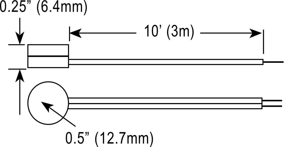 |
Making Temperature Measurements
Place temperature probes in positions to take desired measurements. When measuring surface temperatures, solid mechanical contact is important.
Use Spindle Error Analyzer (SEA) Software to extract temperature readings.
Block Diagram – Temperature
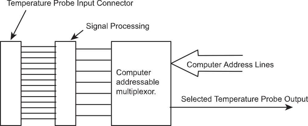
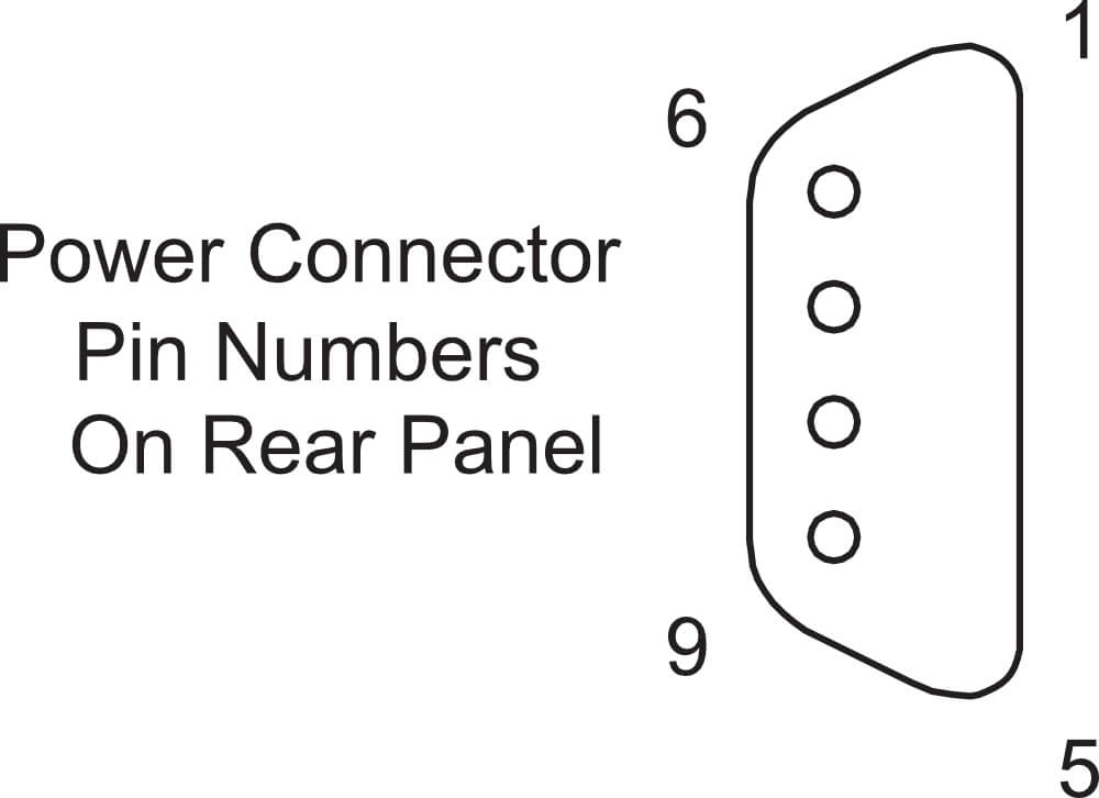
Connections to Temperature Probes
The two wires of each temperature probe are connected according to the chart below. The probes are by nature unpolarized so there is no differentiation between the two conductors.
| Pin Numbers | Connection | Pin Numbers | Connection | 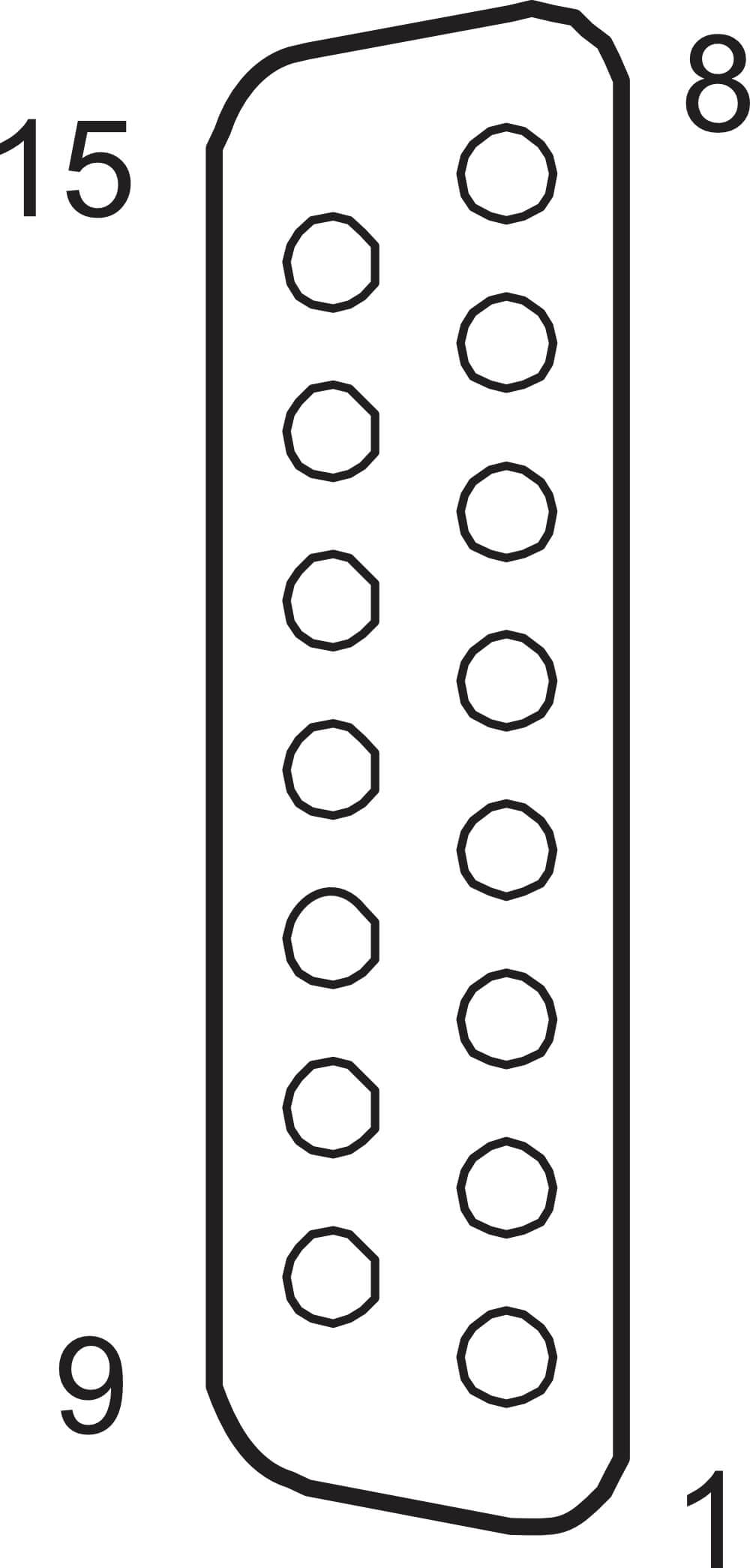 |
| 1, 9 | Probe 1 (T1) | 5, 13 | Probe 5 (T5) | |
| 2, 10 | Probe 2 (T2) | 6, 14 | Probe 6 (T6) | |
| 3, 11 | Probe 3 (T3) | 7, 15 | Probe 7 (T7) | |
| 4, 12 | Probe 4 (T4) | 8 | No Connection |
TMP190 Temperature Specifications1
| Accuracy | ±1.8 °F@40 °F – 180 °F | ±1. 0°C@4°C – 8 2°C |
| Output Voltage | ±10VDC | |
| Measuring Range | 40 °F – 180 °F | 4 °C – 82 °C |
| Temperature Probe Interchangeability Error | ±0.2 °F @ 68 °F | ±0.1 °C @ 20 °C |
1Shifts as high as 4 °C may occur in high EMI conditions (10 V/m).
Encoder/Index Pulse Input
The TMP190 also processes encoder and index pulse inputs for use by the Spindle Error Analyzer. The module performs basic signal processing on the incoming signal then passes the conditioned signal to the data acquisition hardware for analysis by the software.
By definition, index pulses occur once during each revolution of the spindle. Encoder pulses occur many times per revolution. Both are used to provide angular location information to software during a measurement of a rotating target.
Encoder and Index LEDs
To help verify encoder and index pulse operation, green LEDs indicate activity on the encoder and index inputs by flashing at half the frequency of the corresponding input signal.
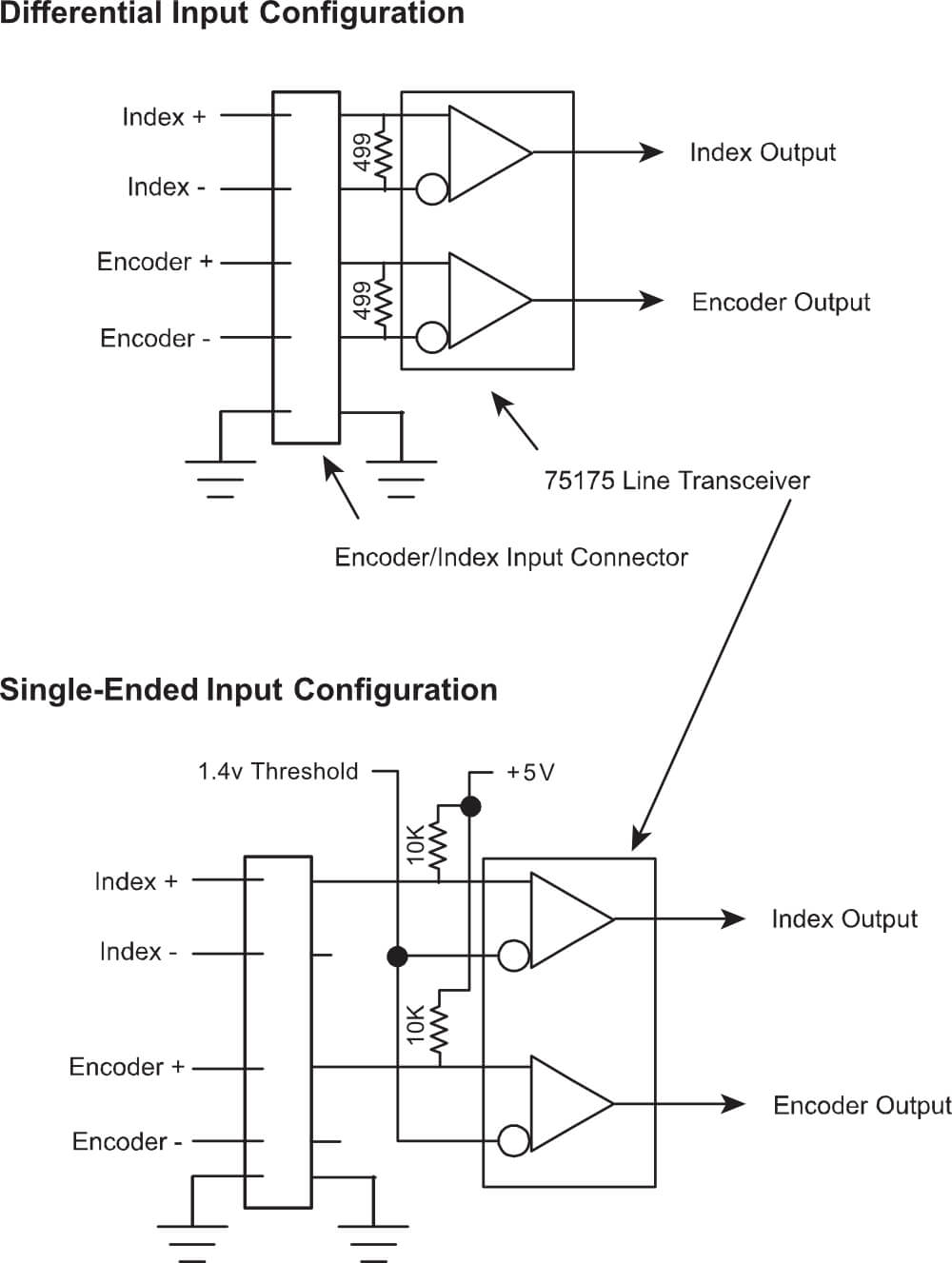
Single-Ended or Differential Inputs
Encoder and index inputs can be configured as single-ended or differential.
In single-ended mode, the signal is measured between the + input and ground. In differential mode, the signal is measured between the + and – inputs.
Differential inputs are less susceptible to noise and interference. Noise and interference from the measurement environment is often injected equally into both wires from the encoder or index generator. When the signal is taken differentially, the noise and interference is canceled resulting in a cleaner signal.
The front panel switch selects the operating mode.
Connections – Encoder/Index
DC power is available on the connector to power encoders or proximity switches.
| Pin Number | Signal | 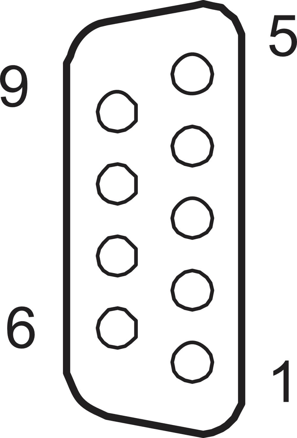 |
| 1 | Ground | |
| 2 | Ground | |
| 3 | +5 VDC, 200 mA max. with self-resetting fuse | |
| 4 | Ground | |
| 5 | +15 VDC, 10 0mA max. with self-resetting fuse | |
| 6 | – Index input, ±12 V Max. | |
| 7 | + Index input, ±12 V Max. | |
| 8 | – Encoder input, ±12 V Max. | |
| 9 | + Encoder input, ±12 V Max. |
Block Diagram – Encoder/Index
Elite Series Enclosures
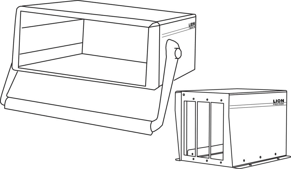
Elite Series enclosures provide housing and critical signals to Elite Series modules. Sensor output signals are available via a rear-panel high-density connector which is configured for direct connection to National Instruments™ data acquisition hardware.
The specific Elite Series enclosure model number indicates the maximum number of slots available for plug-in modules as well as other features:
| Model | Number of Module Slots | Input Power | Tin-up Handle | Mounting Flanges |
|
EN191 |
1 | ±15 VDC | No | Yes |
| EN192 | 2 | ±15 VDC | No | Yes |
| EN193 | 3 | ±15 VDC | No | Yes |
| EN196 | 6 |
100-250 VAC 50/60 Hz |
Yes | No |
| EN198 | 8 |
100-250 VAC 50/60 Hz |
Yes | No |
| Model | Power Input | Note |
| EN191, EN192, EN193 |
±15 VDC ±5%, 400mA Maximum (A power supply is included with orders) |
To maintain maximum resolution use a linear power supply or a power supply with switching frequency greater than 100 kHz such as Lion Precision Power Supply P014-5040. To maintain CE compliance, use the included power supply or equivalent CE compliant model. |
| EN196, EN198 |
100-250 VAC, 50/60 Hz, 250 VA Maximum |
EN191, EN192, EN193 Power Connector
| Pin | Connection |
| 1 | Ground |
| 3 | -15 VDC |
| 4 | +15 VDC |
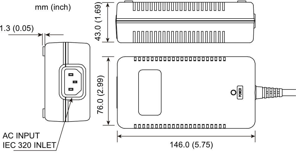
EN191, EN192, and EN193 systems include an external power supply. The supply has a connector which allows direct connection to the enclosure.
This supply features a high-frequency (100kHz) switching supply. The high switching frequency allows the sensing modules to operate at maximum resolution.
| DC Output Voltage |
+15 VDC ; 2.0 A -15 VDC ; 1.0 A |
| AC Input Voltage |
100-240 VAC, 50/60 Hz, 1.35 A max |
DAQ Connector Pinout
All unlisted pins are reserved for proprietary use by Lion Precision and should not be connected to external contacts.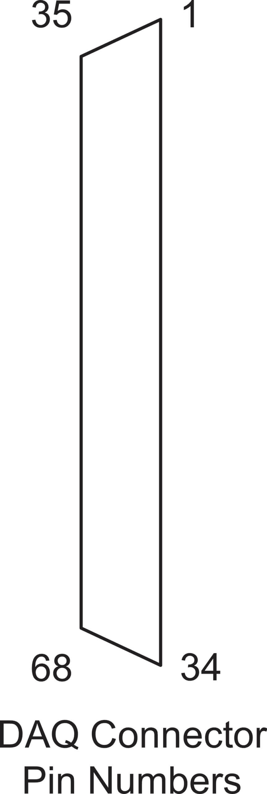
| Pin | Output Signals |
| 11 | Encoder |
| 12, 12, 15, 18, 53 | Digital Ground |
| 29, 32, 64, 67 | Analog Ground |
| 23 | – Analog Out; Channel 8 |
| 25 | + Analog Out; Channel 7 |
| 26 | – Analog Out; Channel 6 |
| 28 | + Analog Out; Channel 5 |
| 30 | + Analog Out; Channel 4 |
| 31 | – Analog Out; Channel 3 |
| 33 | + Analog Out; Channel 2 |
| 34 | – Analog Out; Channel 1 |
| 57 | + Analog Out; Channel 8 |
| 58 | – Analog Out; Channel 7 |
| 60 | + Analog Out; Channel 6 |
| 61 | – Analog Out; Channel 5 |
| 63 | – Analog Out; Channel 4 |
| 65 | + Analog Out; Channel 3 |
| 66 | – Analog Out; Channel 2 |
| 68 | + Analog Out; Channel 1 |
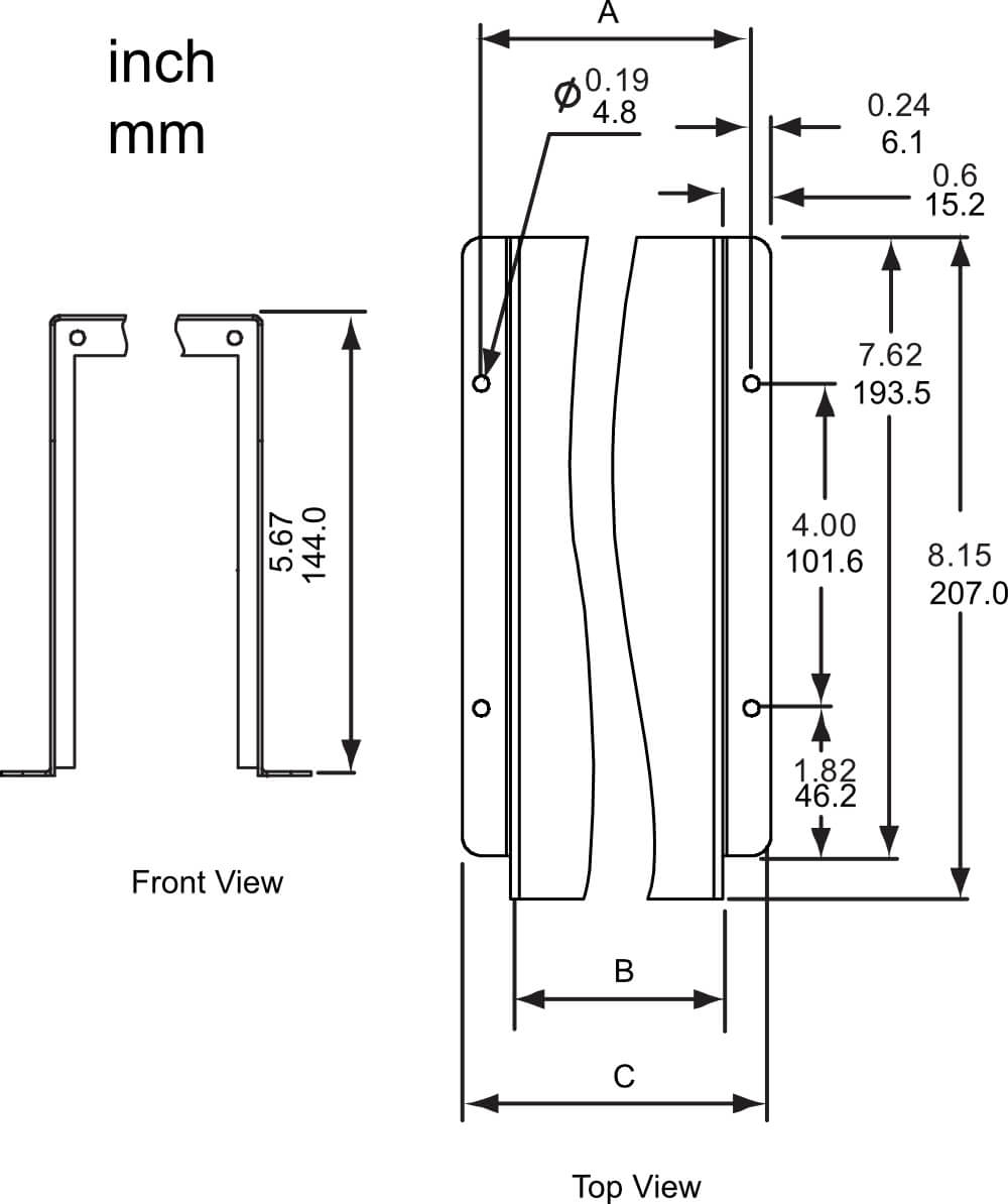
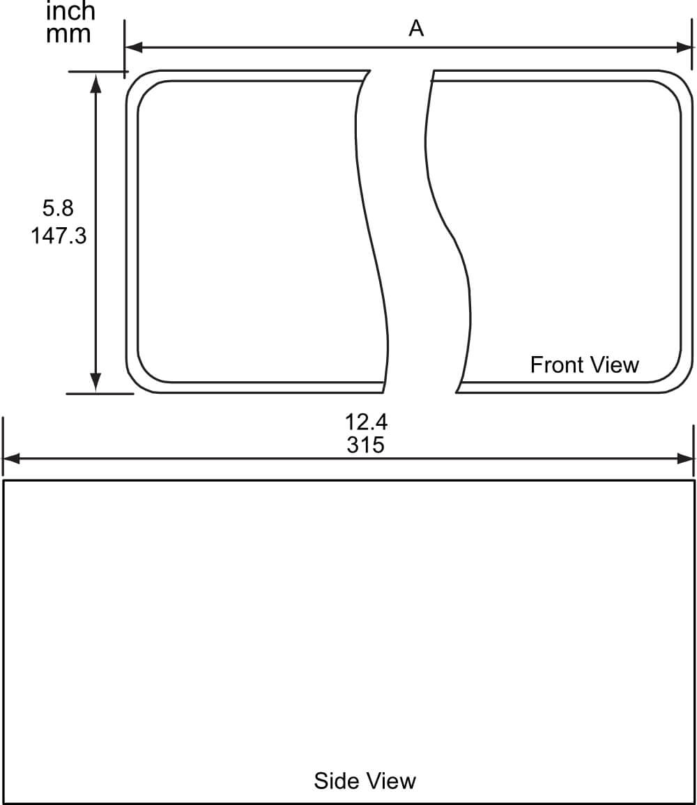
Mechanical Specifications: EN191, EN192, EN193
| Model | A | B | C |
| EN191 |
3.33″ 84.6 mm |
2.606″ 66.2 mm |
3.806″ 96.7 mm |
| EN192 |
4.73″ 120.1 mm |
4.006″ 101.8 mm |
5.206″ 132.2 mm |
| EN193 |
6.13″ 155.7 mm |
5.406″ 137.3 mm |
6.606″ 167.8 mm |
Mechanical Specifications: EN196, EN198
| Model | A |
| EN196 |
10.1″ 257 mm |
| EN198 |
14.3″ 364 mm |
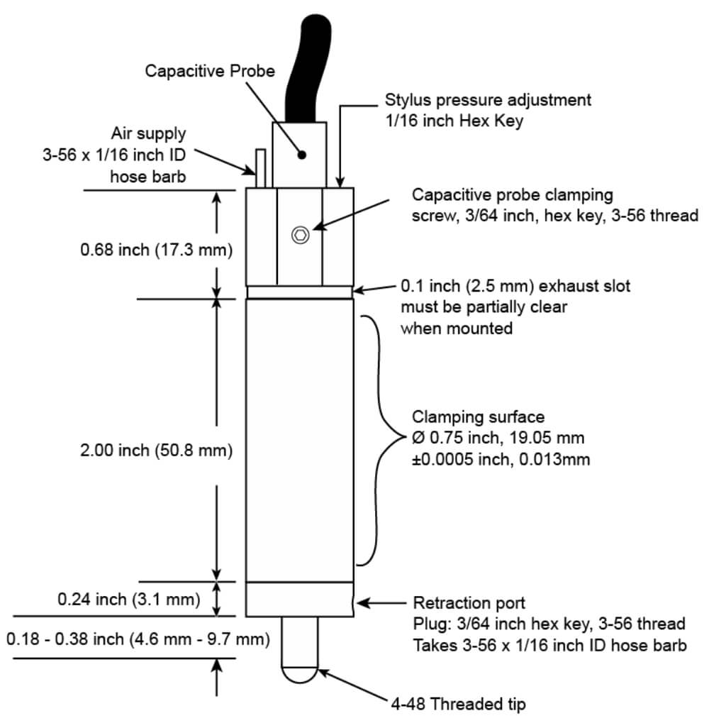
ACCESSORIES: Air-Bearing C-LVDT: Capacitive LVDT-Type Contact Sensor
The Air-Bearing C-LVDT converts a capacitive sensor using a standard capacitive probe into a high-precision contact displacement sensor similar to an LVDT. The capacitive probe is installed in the top of the C-LVDT body where it measures the location of a target connected on the inside end of the stylus. The C-LVDT uses a linear air-bearing for nearly frictionfree movement of the stylus, and the porous carbon air bearing is square to prevent stylus rotation. Adjustable air pressure for extending the stylus provides for contact forces less than one gram, and the C-LVDT features a retraction port through which application of air pressure will retract the stylus.
The C-LVDT uses an interchangeable diamond tip. Diamond has been selected over ruby for the following reasons:
- Low Friction – Side forces cause less lateral deflection from moving targets and less hysteresis on direction reversal.
- Highly Polished Surface – Diamond accepts and holds a high polish, minimizing the possibility of scratching the measured surface.
- Minimal Wear – Increased accuracy and longer life.
Contact Force Adjustment There is a contact force adjustment screw located on the end of the probe body near the cable exit. Use a 1/16″ hex key to turn the adjustment clockwise to increase the contact force or counter clockwise to decrease it. Contact force is also a function of the air pressure applied to the C-LVDT. To maintain constant contact force, supplied air pressure must be held constant.
Air Exhaust
The 0.1″ slot around the body near the top of the C-LVDT is where air is exhausted. Do not clamp the C-LVDT over this ring. The ring must remain at least partially clear at all times for proper operation of the C-LVDT.
Specifications
| Measurement Range | 0.5 mm, 0.020 inch |
| Contact Force | 0.2 g to 100 g |
| Radial Stiffness | < 0.25 μm/g |
| Bearing | Linear, porous air bearing |
| Diamond Tip |
Radius: 3.175 mm, 0.125 inch Mount: 4-48AGD Thread |
| Weight of Moving Mass | 4.2 g |
| Air Connection | 1/16 inch ID flexible tubing |
| Air Consumption | 3-7 lpm, 0.10-0.25 cfm |
| Operating Air Pressure | 420-480 kPa, 60-70 psi |
| Air Requirement | Dry, filtered to less than 5 μm particle size |
Mechanical Detail