Capacitive Application Note LA03-0030
Copyright © 2007 Lion Precision. www.lionprecision.com
Thickness Measurement Summary
Figure 1 – Single-channel thickness measurements assume the part is flat and perfectly seated against the reference.
Details two methods of capacitive, noncontact thickness measurement of a conductive target: Single Channel (Good), and Dual-Channel (Best). The high resolution of capacitive sensors results in accurate, high resolution, noncontact measurement of thickness.
Single-Channel Thickness Measurement Method
Single-channel thickness measurements (Fig. 1) measure the location of the top surface of the part under test while the part rests on a reference surface. As with many noncontact applications, in-process measurements are relative to a reference measurement. A known thickness is established as a reference point and all subsequent measurements indicate the amount of deviation from that reference.
Figure 2 – Deformed parts and reference surfaces or foreign matter between the reference and the part create a thickness measurement error in single-channel systems.
Basic Single-Channel Thickness Measurement Procedure
- Place a conductive part of known thickness on the reference surface.
- Adjust sensor to measure the top surface of the part. The sensor should be positioned near the center of its measurement range to allow for positive and negative deviations from the reference measurement.
- Adjust the sensor output for zero volts or a displayed reading of zero if a measurement display is being used.
- Replace the reference part with a part to be measured.
- Read the deviation in thickness from the display or calculate the deviation from the output voltage.
Accuracy Limitations of the Single-Channel Method
The single-channel method assumes the part is perfectly flat against the reference surface. Any deformity of the part or the reference surface will result in an error in the thickness measurement. Also, any foreign matter, including air, between the part and the reference surface will also create an error (Fig. 2).
Dual-Channel Thickness Measurement Method
Figure 3 – Dual-channel systems compensate for deformities in the part or resting surface by measuring changes in position of the part’s bottom and top surface.
Dual-channel thickness measurements place the part to be measured between two sensors (Fig. 3). Each side of the part is measured by a separate sensor. The sum of the measurements from the two sensors provides the final measurement of thickness (Fig. 4).
If the part moves toward one sensor, it moves away from the other; the changes in the sensors outputs will cancel each other. This eliminates the errors that would result from single-channel problems with deformity and/or contact with the reference surface.
The part can be measured with one sensor mounted in the resting surface, or the part can be otherwise suspended between the two sensors.
As with many noncontact applications, measurements are relative to a reference measurement. A known thickness is established as a reference point and all subsequent measurements indicate the amount of deviation from that reference.
Figure 4 – Summing the two sensor channels produces a “thickness only” output by canceling changes of part position between the sensors.
Basic Dual-Channel Procedure
- Place a conductive part of known thickness between the two sensors.
- Adjust sensor positions to measure the top and bottom surfaces of the part. The sensors should be positioned near the center of measurement range to allow for positive and negative deviations from the reference measurement.
- Adjust the sensor outputs for zero volts and a displayed reading of zero when using a measurement display with summing capabilities (see recommendations below).
- Replace the reference part with a part to be measured.
- Read the thickness deviation from the display with summing capabilities or calculate the deviation by adding the two output voltages and converting to dimensional units.
Dual-Channel Example
The following example uses two sensors which are calibrated for 10V/1mm. Condition 1 sets a 1mm thick target as a reference at 0 volts. Condition 2 shows the effect of moving the 1mm thick target closer to one sensor. Condition 3 shows the uncentered measurement of a test part which is 1.5mm thick.
Recommended Equipment
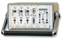 The Elite Series of capacitive sensor systems can provide precision sensing capabilities (CPL190 Driver) with a display module (MM190) that displays the measurement in actual dimensional units. The MM190 can also perform the summing operation for dual-channel thickness measurements. Sensor Plug&Play compatibility makes for easy use with LabView™.