USER’S GUIDE for the
CPL490
Wide Bandwidth Picometer Capacitive Displacement Sensor
TABLE OF CONTENTS
- Approvals and Safety Considerations
- Helpful Technical Support Documents Online
- CPL490 Wide Bandwidth Picometer Capacitive Displacement Sensor
- Multiple Channel Measurements
- Specifications
- Changing CPL190/290/490 Bandwidth Settings
- Elite Series Enclosures
- Accessories
Approvals and Safety Considerations
The Elite Series is compliant with the following CE standards:
Safety: EN 61010-1:2010
EMC: IEC 61326-1:2013, IEC 61326-2-3:2013
To maintain compliance with these standards, the following operating conditions must be maintained:
- All I/O connecting cables must be shielded and less than three meters in length
- AC power cables must be rated at a minimum of 250 V and 5 A
- AC power must be connected to a grounded mains outlet rated less than 20A
- Use the included CE approved power supply with 1-, 2-, and 3- slot enclosures. If an alternative power supply is used, it must have equivalent CE certification and provide safety isolation from the mains according to IEC60950 or 61010.
- Sensors must not be attached to parts operating at hazardous voltages in excess of 33VRMS or 70VDC
Use of the equipment in any other manner may impair its safety and EMI protections.
The sensing tips of capacitive probes produce voltages as high as 70 Vrms. These are high frequency voltages with very low power so they pose no danger. Normally when the probe tip is touched, the probe stops functioning and voltage is reduced to near zero. But under certain circumstances, the voltage may cause a slight tingle or burning sensation, especially with the second generation probes used with the CPL490. For maximum performance probe tips should remain free of oils or other contaminants.
For these reasons, it is recommended the probe tips not be touched.
Helpful Technical Support Document Online
Lion Precision’s web site has a large selection of technical documents (TechNotes and Application Notes) in the Technical Library. These documents provide detailed descriptions of the operation and use of Lion Precision high-performance sensors.
The Technical Library can be accessed at: www.lionprecision.com/technical-library/
Some of the titles include:
- Understanding Sensor Resolution Specifications and Effects on Performance
- Capacitive Sensor Theory of Operation
- Error Sources: Probe/Target Angle
- Capacitive Sensors in Vacuum
- Capacitive Sensor Phasing and Ungrounded Targets
- Capacitive Probe Cabling Considerations
- Elite Series Phase/Amplitude Frequency Response
- Z-Height Measurement with Capacitive and Eddy-Current Sensors
- Thickness Measurement with Capacitive Sensors
- Glue Sensing with Capacitive Sensors
Description
The CPL490 Capacitive Sensor is a very high precision, noncontact measurement device. The output voltage changes in linear proportion to changes in the gap between the probe and the target. The sensor is normally used to measure conductive targets, but it can also be used with nonconductive targets in some applications. For more information about measuring nonconductors, visit the Technical Library at www.lionprecision.com or call for assistance.
The CPL490 only works with 2nd Generation Probes which include integral electronics.
Basic Operation
The output voltage is accessed via the front panel BNC connector, or by a data acquisition system via the high-density connector on the rear of the enclosure. This connector can connect directly to many National Instruments™ data acquisition products. See the enclosure section of this manual for specifics on the system DAQ connector (page 19).
As the gap between the probe and target changes, the output voltage will change accordingly. As the probe approaches the target, the output voltage will become more positive.
Note: “Near” and “Far” lights (red) indicate that the probe is out of its calibrated range and the output is not guaranteed to be accurate even though the voltage may continue to change.
Probes are calibrated to specific modules. With multiple channel systems, be sure the number on the probe cable (near the connector) matches the number on the module handle. Calibration detail is provided on calibration sheets shipped with the product.
Noncontact sensors normally measure changes from a reference position.
Making a Basic Measurement
- Connect probe to module
- Set the target to a reference position or condition
- Mount probe near target (probes should be mounted by the 8 mm diameter probe body which extends from the larger probe electronics housing)
- Adjust the probe position until the Near/Far indicator is at center position
- Use the Zero adjustments to adjust the output voltage to zero (optional)
- As the probe/target gap changes, the output voltage will change accordingly
Interpreting the Output Voltage
The amount of change of the output voltage for a given change in the probe/target gap is called Sensitivity. The sensitivity of the sensor is listed on the calibration sheets which arrived with the sensor.
Change in gap calculation:
Gap Change = Voltage Change / Sensitivity
For example: With a sensitivity of 1 V/2 μm and a voltage change of 3 V, the gap change would be 6 μm (3/0.5).
Overview of Front Panel Controls, Indicators and Connectors
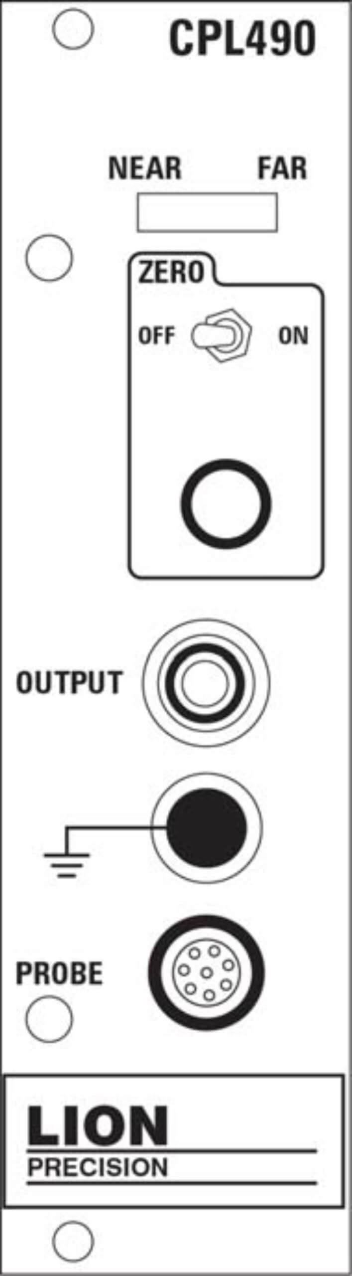 Zero Adjust
Provides a DC shift of the analog output voltage after the probe is initially positioned. The adjustment has a range of ±1 VDC. Typically, the analog output voltage is adjusted to zero volts at range center. When the Zero switch is in the off position, the zero adjustment has no effect.
Calibrated Range Indicator (Near Far)
Indicates where the probe is within its calibrated range. Green LEDs indicate that the probe is in its calibrated range and the output voltage is an accurate representation of the target position. Red LEDs indicate that the probe is out of range. When the probe is out of range, the output voltage may not be an accurate indication of the target position even if it is still within the ±10 VDC range. The Zero adjust has no effect on the Calibrated Range Indicator.
Provides connection to the analog output voltage, which is linearly proportional to the distance between the probe and the surface of the object being measured. A typical output voltage range is ±10 VDC. The specific range is listed on the calibration sheet shipped with the device.
The analog output provided on the data acquisition (DAQ) connector on the rear of the enclosure is differential. See the enclosure section of this manual for specifics on the system DAQ connector (page 19).
A banana-plug cable can be connected here for grounding the target. In most cases, separate grounding of the target is not necessary. If the target is not grounded through another path, and the output exhibits excessive electrical noise, grounding the target may reduce the output noise. When low-noise operation is critical, separate grounding is recommended even if the target is well grounded through another path.
Connect the probe by aligning the red dots on the connectors and inserting the probe connector.
To disconnect the probe, pull on the knurled barrel of the probe connector to release it. DO NOT PULL ON THE CABLE.
Multiple Channel Measurements
Using multiple sensors on the same target requires that the sensor excitation voltages be appropriately selected. Systems ordered for multiple channel use on the same target will be specially calibrated to avoid inter-channel interference. Using multiple CPL490s together which are not so calibrated may produce interference in the output voltages of all channels. Sensors that will be used together to measure the same object must be ordered together so they can be appropriately calibrated. Using multiple sensors not so calibrated may not provide accurate results.
Specifications
| Linearity Error | 0.2% F.S. |
| Error Band | 0.3% F.S. |
| Standard Bandwidth (-3 db) | Selectable: 1 kHz, 10 kHz, 15 kHz, 50 kHz Bandwidths are -10%+30% |
| Meets ANSI/ASME B5.54 Standard | Yes |
| Operating Temperature | 15-40 °C |
| Thermal Stability | 0.02-0.04% F.S., Probe/Range dependent |
| Oscillator Frequency |
Probe/Calibration dependent. 6.4 MHz typical |
| Output Impedance | 0 Ω |
| Output Max Voltage | ±13.5 VDC |
| Output Max Current | 10 mA |
These specifications are typical for standard components and calibrations. Customizations can affect performance. Check the calibration sheet shipped with the product for specific details on your system.
In high EMI environments (10 V/m), output noise may rise to 0.5 VRMS and DC value may shift 0.7 VDC.
Changing CPL190/290/490 Bandwidth Settings
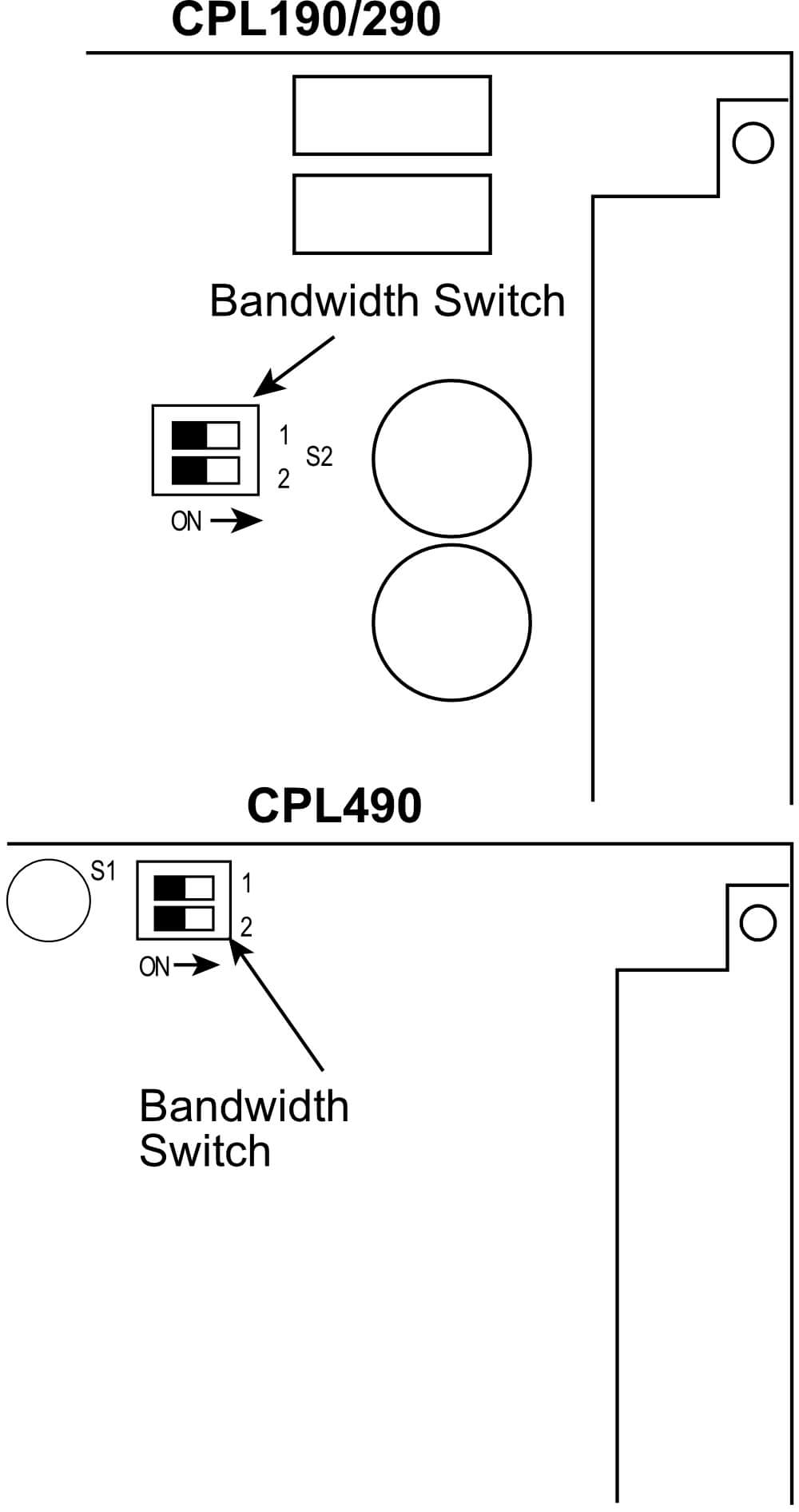 The CPL190/290/490 provides a two-position DIP switch for setting bandwidth.
When changing bandwidth, change all modules in the system. Bandwidth is a system-wide setting; bandwidth switches on the modules within a system are interconnected.
All of the bandwidth switches must be in the same position for predictable results.
This switch is located as shown in the drawings at the right. The following table shows the bandwidths available and their associated dip switch settings.
Bandwidths listed are approximate. Actual values depend on the probe and calibration.
| CPL190/290(S2) | CPL490(S1) | 2 | 1 | Notes |
| 15 kHz | 50 kHz | OFF | OFF | Computer control of bandwidth requires this setting (OFF, OFF) |
| 10 kHz | 15 kHz | OFF | ON | |
| 1 kHz | 10 kHz | ON | OFF | |
| 100 Hz | 1 kHz | ON | ON |
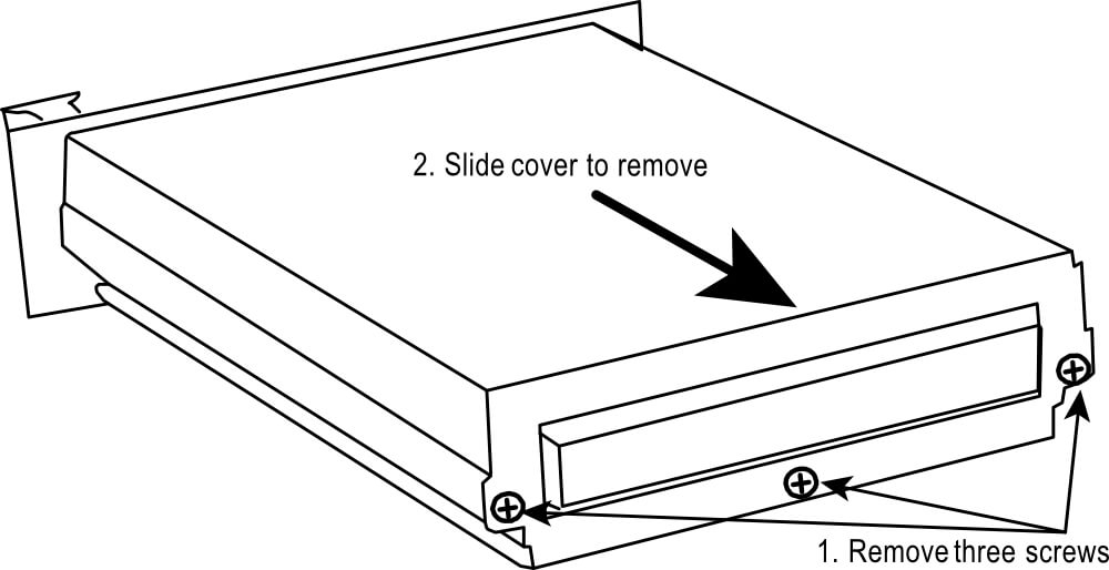
Bandwidth DIP Switch Access
Be careful to only change switches and jumpers as directed in this manual. Any other changes will affect the calibration of the module.
Elite Series Enclosures
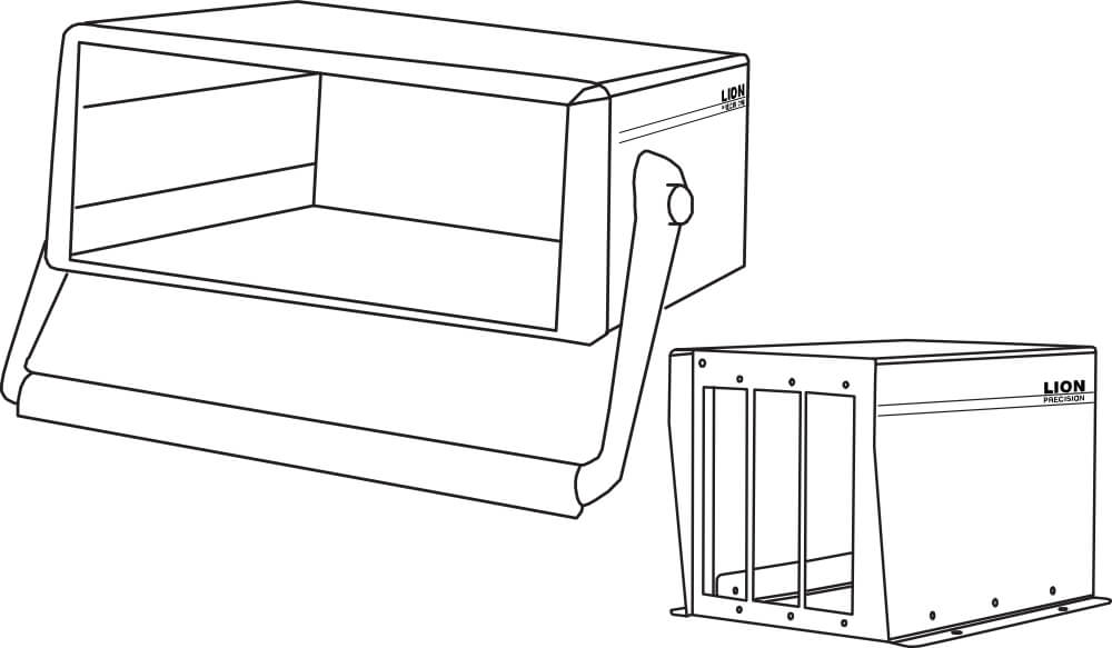
Elite Series enclosures provide housing and critical signals to Elite Series modules. Sensor output signals are available via a rear-panel high-density connector which is configured for direct connection to National Instruments™ data acquisition hardware.
The specific Elite Series enclosure model number indicates the maximum number of slots available for plug-in modules as well as other features:
| Model | Number of Module Slots | Input Power | Tin-up Handle | Mounting Flanges |
|
EN191 |
1 | ±15 VDC | No | Yes |
| EN192 | 2 | ±15 VDC | No | Yes |
| EN193 | 3 | ±15 VDC | No | Yes |
| EN196 | 6 |
100-250 VAC 50/60 Hz |
Yes | No |
| EN198 | 8 |
100-250 VAC 50/60 Hz |
Yes | No |
| Model | Power Input | Note |
| EN191, EN192, EN193 |
±15 VDC ±5%, 400mA Maximum (A power supply is included with orders) |
To maintain maximum resolution use a linear power supply or a power supply with switching frequency greater than 100 kHz such as Lion Precision Power Supply P014-5040. To maintain CE compliance, use the included power supply or equivalent CE compliant model. |
| EN196, EN198 |
100-250 VAC, 50/60 Hz, 250 VA Maximum |
EN191, EN192, EN193 Power Connector
| Pin | Connection |
| 1 | Ground |
| 3 | -15 VDC |
| 4 | +15 VDC |
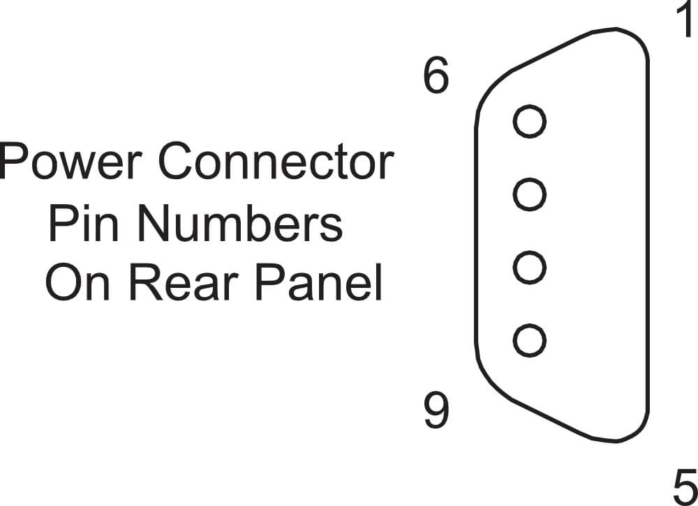
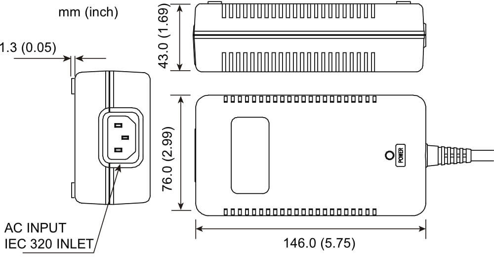
EN191, EN192, and EN193 systems include an external power supply. The supply has a connector which allows direct connection to the enclosure.
This supply features a high-frequency (100kHz) switching supply. The high switching frequency allows the sensing modules to operate at maximum resolution.
| DC Output Voltage |
+15 VDC ; 2.0 A -15 VDC ; 1.0 A |
| AC Input Voltage |
100-240 VAC, 50/60 Hz, 1.35 A max |
DAQ Connector Pinout
All unlisted pins are reserved for proprietary use by Lion Precision and should not be connected to external contacts.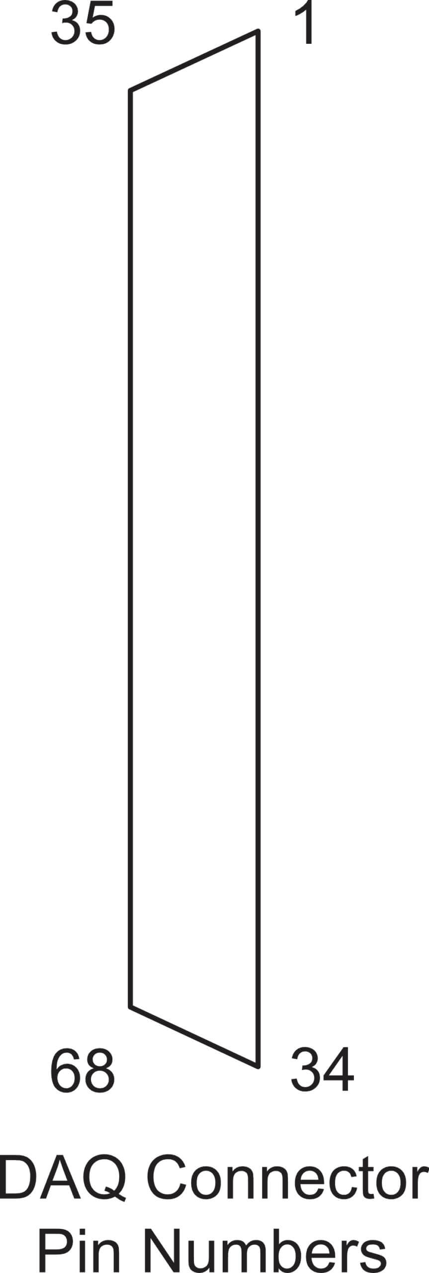
| Pin | Output Signals |
| 11 | Encoder |
| 12, 12, 15, 18, 53 | Digital Ground |
| 29, 32, 64, 67 | Analog Ground |
| 23 | – Analog Out; Channel 8 |
| 25 | + Analog Out; Channel 7 |
| 26 | – Analog Out; Channel 6 |
| 28 | + Analog Out; Channel 5 |
| 30 | + Analog Out; Channel 4 |
| 31 | – Analog Out; Channel 3 |
| 33 | + Analog Out; Channel 2 |
| 34 | – Analog Out; Channel 1 |
| 57 | + Analog Out; Channel 8 |
| 58 | – Analog Out; Channel 7 |
| 60 | + Analog Out; Channel 6 |
| 61 | – Analog Out; Channel 5 |
| 63 | – Analog Out; Channel 4 |
| 65 | + Analog Out; Channel 3 |
| 66 | – Analog Out; Channel 2 |
| 68 | + Analog Out; Channel 1 |
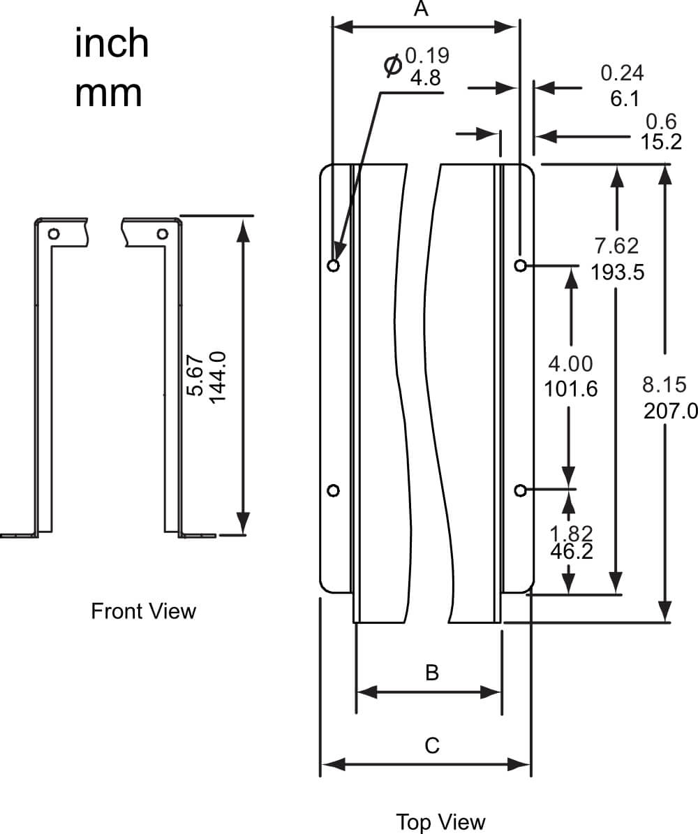
Mechanical Specifications: EN191, EN192, EN193
| Model | A | B | C |
| EN191 |
3.33″ 84.6 mm |
2.606″ 66.2 mm |
3.806″ 96.7 mm |
| EN192 |
4.73″ 120.1 mm |
4.006″ 101.8 mm |
5.206″ 132.2 mm |
| EN193 |
6.13″ 155.7 mm |
5.406″ 137.3 mm |
6.606″ 167.8 mm |
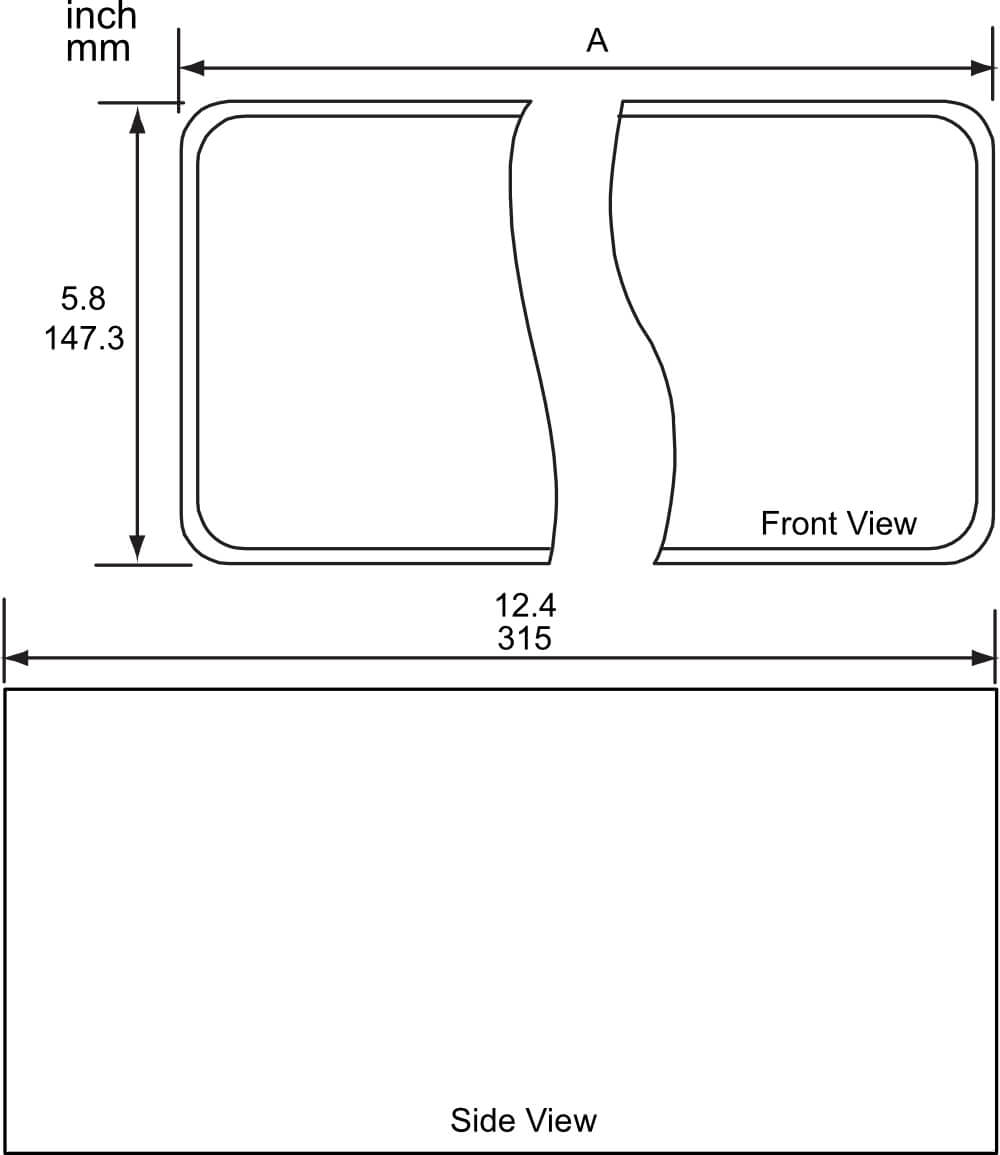
Mechanical Specifications: EN196, EN198
| Model | A |
| EN196 |
10.1″ 257 mm |
| EN198 |
14.3″ 364 mm |
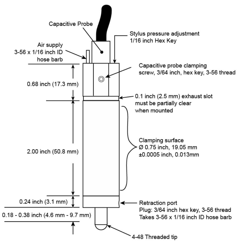
ACCESSORIES: Air-Bearing C-LVDT: Capacitive LVDT-Type Contact Sensor
The Air-Bearing C-LVDT converts a capacitive sensor using a standard capacitive probe into a high-precision contact displacement sensor similar to an LVDT. The capacitive probe is installed in the top of the C-LVDT body where it measures the location of a target connected on the inside end of the stylus. The C-LVDT uses a linear air-bearing for nearly frictionfree movement of the stylus, and the porous carbon air bearing is square to prevent stylus rotation. Adjustable air pressure for extending the stylus provides for contact forces less than one gram, and the C-LVDT features a retraction port through which application of air pressure will retract the stylus.
The C-LVDT uses an interchangeable diamond tip. Diamond has been selected over ruby for the following reasons:
- Low Friction – Side forces cause less lateral deflection from moving targets and less hysteresis on direction reversal.
- Highly Polished Surface – Diamond accepts and holds a high polish, minimizing the possibility of scratching the measured surface.
- Minimal Wear – Increased accuracy and longer life.
Contact Force Adjustment There is a contact force adjustment screw located on the end of the probe body near the cable exit. Use a 1/16″ hex key to turn the adjustment clockwise to increase the contact force or counter clockwise to decrease it. Contact force is also a function of the air pressure applied to the C-LVDT. To maintain constant contact force, supplied air pressure must be held constant.
Air Exhaust
The 0.1″ slot around the body near the top of the C-LVDT is where air is exhausted. Do not clamp the C-LVDT over this ring. The ring must remain at least partially clear at all times for proper operation of the C-LVDT.
Specifications
| Measurement Range | 0.5 mm, 0.020 inch |
| Contact Force | 0.2 g to 100 g |
| Radial Stiffness | < 0.25 μm/g |
| Bearing | Linear, porous air bearing |
| Diamond Tip |
Radius: 3.175 mm, 0.125 inch Mount: 4-48AGD Thread |
| Weight of Moving Mass | 4.2 g |
| Air Connection | 1/16 inch ID flexible tubing |
| Air Consumption | 3-7 lpm, 0.10-0.25 cfm |
| Operating Air Pressure | 420-480 kPa, 60-70 psi |
| Air Requirement | Dry, filtered to less than 5 μm particle size |
Mechanical Detail