Capacitive Application Note LA03-0022
Copyright © 2012 Lion Precision. www.lionprecision.com
Summary
Locating thousands of fragile mirrors in an orbital telescope using capacitive sensors to monitor mirror position within 1 µm and 1 microradian (1 µrad).
The Next Generation X-Ray Optics
NASA is developing the next generation of X-Ray optics which could be used in an orbiting X-Ray Observatory. The “lens” consists of thousands of mirrors positioned to reflect X-rays at a shallow angle with a focal length of 3-10 meters. Locating and fixing the mirrors in position is the primary challenge of the project. Creating focus at the long focal lengths requires a mirror angular position tolerance of only 1 µRadian, and the precisely shaped mirrors, when mounted, must distort less than 0.1 µm from their free, unmounted state. And of course any such assembly must be able to hold these positions through launch and deployment.
Fragile Mirrors, High-Precision Mounting
The typical mirror is about the size of a sheet of printer paper and only four times as thick (200 mm X 200 mm X 0.4 mm) and is coated with a 10 nm layer of iridium or gold. The mirrors are so thin, that only 1 mN of force will distort their shape. Thermal expansion is also of concern; a person’s prolonged proximity to a mirror creates a measurable distortion, so the mounting process must add little heat to the structure.
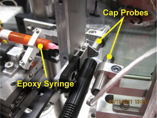
Mirrors are mounted on tabs in the final assembly and fixed in place with UV cured epoxy. The injection and curing of the epoxy are the critical steps. The dynamics of the hydraulic pressure during and immediately after the epoxy’s injection displace the mirror at the points of contact causing distortion and placement changes. The epoxy also expands during the UV cure process which further distorts the mirror.
Monitoring Position During Mounting Operation
High-resolution capacitive displacement sensors (Lion Precision Elite Series sensors) have been used to profile, with nanometer precision, the mirror’s displacement during the bonding process. Having profiled the movements and distortions created by the hydraulic pressure and the UV curing process, the amount of epoxy injected and the timing of the UV cure can be used to control the final mirror position. The capacitive sensors are used during the automated bonding sequence to stop the injection when the mirror distortion reaches a predetermined point. The system then monitors the mirror position during the post-injection epoxy flow. The UV curing process is begun when the mirror reaches a position from which the epoxy cure expansion will move the mirror precisely to its desired position with better than 1 µm of accuracy (see chart below).
Capacitive Sensing System Details
Six capacitive displacement sensors are used in the system – one for each corner of the mirror and two to monitor the mounting tab positions as a reference (photo below, mirror is transparent at camera angle). Capacitive displacement sensors usually require a grounded target to prevent accumulation of charge on the target, but the fragile mirrors cannot be grounded. The Elite Series sensors are designed to prevent this problem; the excitation signals have a 180° phase difference between even and odd numbered channels. This phase arrangement allows half of the sensors to add charge to the mirror while the other half remove charge, thereby eliminating the need for a conductive path to ground (Capacitive Sensors and Ungrounded Targets).
Capacitive Sensors Preferred to Laser
Originally, laser displacement sensors were used in the system. While the lasers provided measurement from a greater distance, an alternative had be found because the lasers’ size made them difficult to mount, and they had insufficient resolution, were too expensive, and generated too much heat. The capacitive sensors are low power/heat devices with high resolutions, and the small size makes mounting easy.
Capacitive System Details
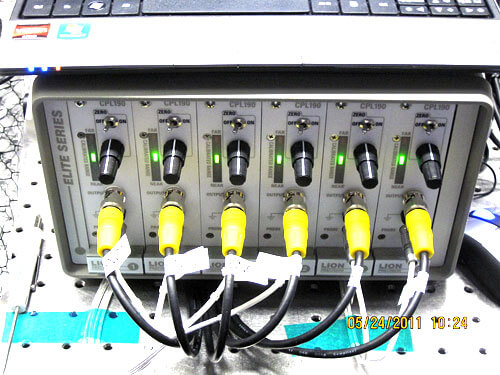
Six CPL190 Drivers in a 6-slot Elite Series Enclosure (EN196)
Six C9.5-5.6 Probes
Calibration: 500 µm Range, 15 kHz Bandwidth, 10 nm rms Resolution
Thanks to Ryan McClelland of NASA for providing data, charts and photos.