Copyright © 2015 Lion Precision. www.lionprecision.com
Summary
This Application Note describes the use and setup of special thread detecting probes with standard Lion Precision eddy-current sensor electronics. Different electronics are required for ferrous versus nonferrous materials.
Introduction
Specially designed thread-sensing probes can be used with standard eddy-current sensor electronics to detect the presence/absence of threads in a hole. Thread sensors generate different output voltages for tapped versus untapped holes.
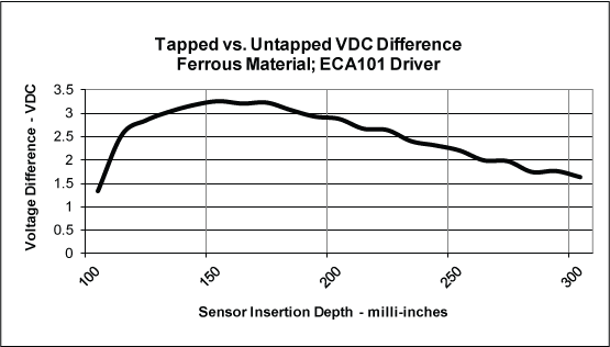
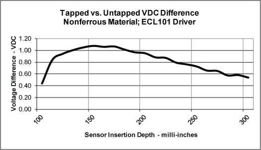
The ECA101 is used for ferrous materials and can create a voltage difference of 3-4 volts between tapped and untapped holes. The ECL101 is used for nonferrous materials and creates a 1.0 volt difference between tapped and untapped holes.
Basic Theory of Operation
Eddy-Current probes are primarily designed as displacement sensors measuring changes of the gap between the sensor and the target. Specially designed thread-dection probes have longer probe-tip extensions which allow for deeper hole penetration and for the magnetic field of the sensing coil to engage the sides of the hole being tested.
The fundamental principle is that an untapped hole’s surfaces are, on average, “closer” to the probe than a tapped hole’s surfaces. This change in average distance from the probe to the surrounding material creates a change in output voltage from the electronics.
Material Differences
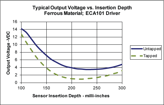
Ferrous Materials (Steel)
Thread sensing in ferrous materials is accomplished with a thread sensing probe and ECA101 driver electronics. The output voltage differences between tapped and untapped holes is substantial as shown below in the charts of typical output voltages.
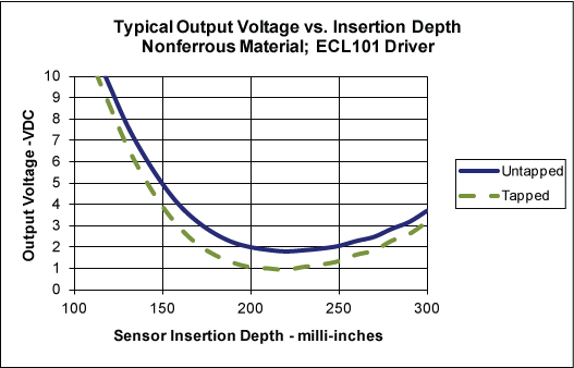
Nonferrous Materials (Aluminum)
Thread sensing in nonferrous materials is accomplished with a thread sensing probe and ECL101 driver electronics. The output voltage differences between tapped and untapped holes are much less than with ferrous materials. This has proven to work reliably but greater consideration must be given to the application as the margin for error is smaller. The charts below show typical output voltages for nonferrous applications.
Selecting a Probe and Driver Electronics
Driver Electronics
The ECA101 used with ferrous materials offers an analog output voltage and a setpoint switched output. The switched output can be used to create a Go/NoGo type indication for thread detection.
The ECL101 used with nonferrous materials has an analog output only which will have to be evaluated by a data acquisition system to determine the presence/absence of threads.
Each driver model manual has a “Thread Sensing” addendum with instructions on how to best setup the sensor for sensing threads.
Thread Sensing Probes
Probe selection is dependent on material type and hole/thread type. Ferrous materials (steel) use the ECA101 Driver; nonferrous materials (aluminum) use the ECL101 Driver.
Select the probe from the tables below:
|
|
||||||||||||||||||||||||||||||||||||||||||||||||||||||
Mechanical and Mounting Considerations
Centering
The output voltage will change if the probe is not perfectly centered in the hole. The change is not large, but especially for nonferrous materials with smaller margin of error, this should be considered when using the probes. Complete details are available in the “Thread Sensing Probe Centering Errors” TechNote LT02-0015.
Protecting the Probe
Severe centering errors or other mishaps may cause the probe to crash into the target. Nonferrous sensor diameters are about 85% of the hole size, while ferrous sensors are about 65% of the hole size. The table below shows typical gap sizes:
|
|
|
|||||||||||||||||||||||||||||||||||||||||||||||||||||||||||||||||||||||||||||||||
Spring-loaded probe mounts can be used to protect probes from damage in case of crash. Three models are available for different probe sizes:
|
|
Model Number |
||
|
SN-08 |
SN-12 |
SN-18 |
|
| Internal Thread (must match probe) |
M8x1 (T5-8) |
M12x1 (T10-12) |
M18x1 (T16) |
| External Thread | M16x1.5 | M22x1.5 | M30x1.5 |
| Maximum Extension | 0.35″ (8.9mm) | 0.41″ (10.4mm) | 0.49″ (12.4mm) |
Thread Sensing Probe Dimensions
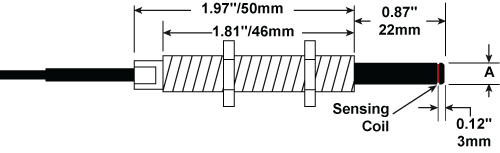
|
Mechanical Specifications |
||
|
Probe |
Dimension “A” |
Body Thread |
| T5BZ | 0.13″ / 3.3mm | M8x1 |
| T6BZ | 0.16″ / 4.1mm | |
| T7BZ | 0.20″ / 5.1mm | |
| T8BZ | 0.23″ / 5.8mm | |
| T10BZ | 0.30″ / 7.5mm | M12x1 |
| T12BZ | 0.37″ / 9.3mm | |
| T16BZ | 0.52″ / 13.1mm | M18x1 |