
USER’S GUIDE for the
TARGA III – Dynamic Runout System
Download PDF File
TABLE OF CONTENTS
- APPROVALS AND SAFETY CONSIDERATIONS
- WELCOME
- HELP
- CALIBRATION
- TARGA III
- PROBE DRIVER
- METER/DISPLAY MODULE
- SPECIFICATIONS
- POWER INPUT CONNECTOR
- SYSTEM MECHANICAL DETAIL
- EXTERNAL POWER SUPPLY
APPROVALS AND SAFETY CONSIDERATIONS
The TARGA III is compliant with the following CE directives:
Safety: 61010-1:2001
EMC: 61326-1, 61326-2-3
To maintain compliance with these standards, the following operating conditions must be maintained:
- All I/O connecting cables must be shielded and less then three meters in length
- AC power cables must be rated at a minimum of 250V and 5A
- AC power must be connected to a grounded mains outlet rated less than 20A
- Use the included CE approved power supply. If an alternative power supply is used, it must have equivalent CE certification and provide safety isolation from the mains according to IEC60950 or 61010.
- Sensors must not be attached to parts operating at hazardous voltages in excess of 33VRMS or 70VDC
Use of the equipment in any other manner may impair the safety and EMI protections of the equipment.
WELCOME
Congratulations on your purchase of a Lion Precision TARGA III Dynamic Runout measurement system. This manual will provide you with all the information you require to get the greatest benefit from your system.
Engineers and maintenance personnel will find the TARGA III invaluable for high precision measurement of dynamic runout at speeds up to 300,000 RPM.
CALIBRATION
Your system was calibrated with the Lion Precision Ultimate Calibrator. This calibrator was designed by Lion Precision and includes a state-of-the-art air slide and motion control system for high-precision calibrations. All of our calibrations are traceable to NIST. Data on the calibration sheets refer to the calibration of the probe when measuring a 1/8″ gage pin. When other size pins are used, the system applies a correction factor to maintain an accurate reading. For specifications on the measurement of TIR and Dynamic Runout, see the specifications section at the end of this manual.
- NOTE:
- Replacement probes must be calibrated to the electronics.
- Replacing the probe without calibration can result in errors of up to 10%.
HELP
TARGA III
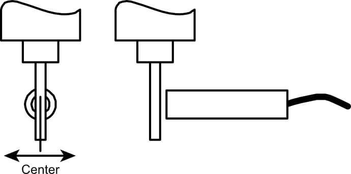
The TARGA III system is designed to measure and display the dynamic runout of high-speed spindles. While it is designed specifically for the PCB drilling industry, it can measure any spindle that can rotate a gage pin. Understanding the relationship between runout and RPM provides information on the best drilling speeds and can indicate out-of-spec spindles.
|
|
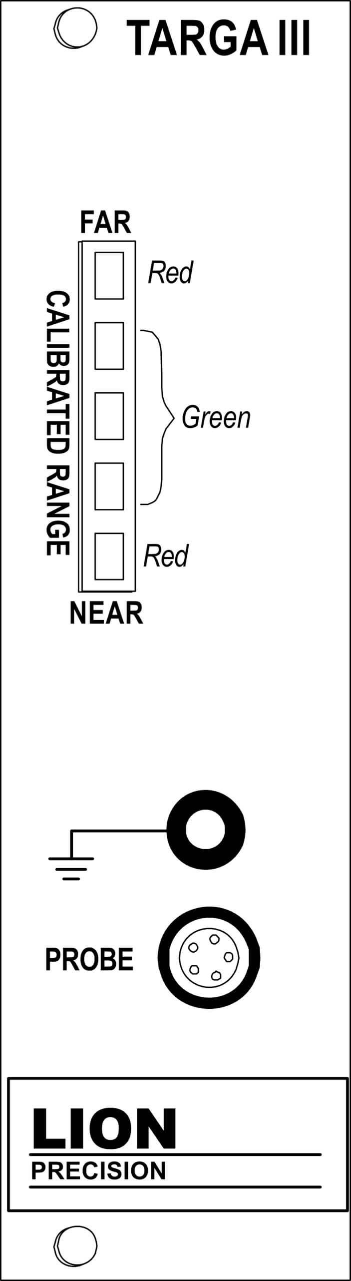
PROBE DRIVER
METER/DISPLAY MODULE
|
The Meter/Display Module displays dimensional values derived from sensor. The displayed value is also provided as an analog voltage at the front panel BNC “Output” connector.
Pressing the appropriate button repeatedly rotates through selections.
|
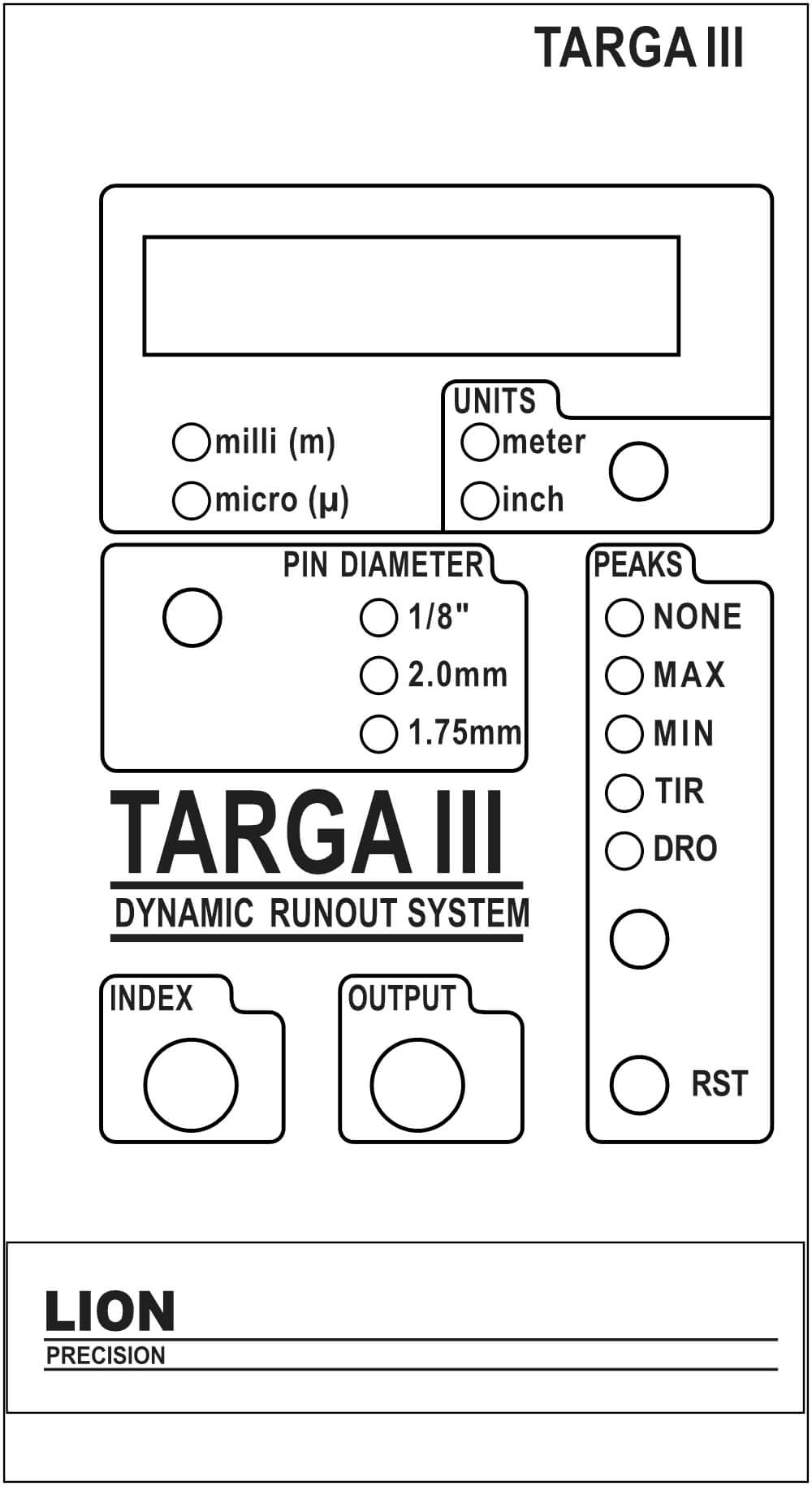 |
Pin Diameter
For accurate measurements, the Targa III must know the size of the pin used as a target. Three choice are available: 1/8″, 2mm, and 1.75mm. Press the button to select the appropriate pin size.
The system is calibrated for a measurement range of 250μm (0.01″) with a 1/8″ pin. The calibrated range is directly proportional to the pin diameter. Smaller diameter pins have a slightly reduced range.
Display Units
The Meter/Display module measures the analog voltage from the sensor and uses digital signal processing to perform peak capture functions. The result is converted to dimensional units for display. The multiplier indicators (milli, micro) combined with the Meter or Inch units indicate the dimensions of the displayed value. The Units button selects either Meter or Inch units.
Peaks
Five options are available:
NONE – Display is real-time measurement value (probe/pin gap).
MAX – Displays the most positive value since the last reset (RST).
MIN – Displays the most negative value since the last reset (RST).
TIR – Displays the maximum difference between the MAX and MIN values since the last Reset (RST). TIR is always a positive value.
DRO – Dynamic Runout displays the current difference between the MAX and MIN values. When the TIR value is reduced, the displayed value will decay to the lower value within approximately one second.
Analog Output (BNC)
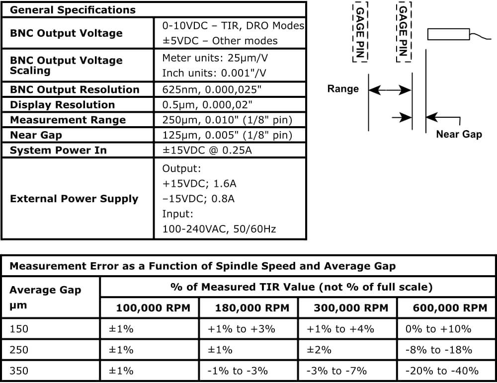
Provides an analog output voltage proportional to the displayed value. With non-TIR readings (NONE, MAX, MIN), the output is ±5VDC; With TIR and DRO readings, output is 0-10VDC. When “Meter” units are selected, the output voltage scaling is 25μm/V; with “Inch” units, the output scaling is 0.001″/V.
Index
If the Targa III is used with an external data acquisition system and computer, then it is possible for the computer to use the Index input to calculate RPM. If your Targa III is not supplied with a separate data acquisition system, then the Index input is not used. The Targa III system does not measure or display RPM directly. For more detail on this application, see Lion Precision TechNote – LT03-0026 Targa III Index Connector Usage available at www.lionprecision.com; click on Technical Library.
SPECIFICATIONS
 |
POWER INPUT CONNECTOR
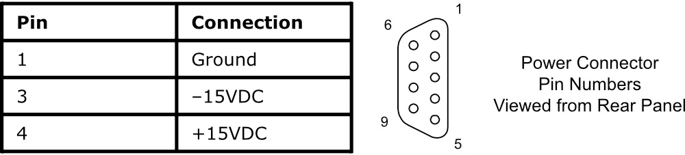 |
SYSTEM MECHANICAL DETAIL
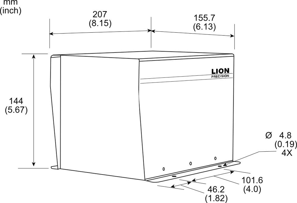 |
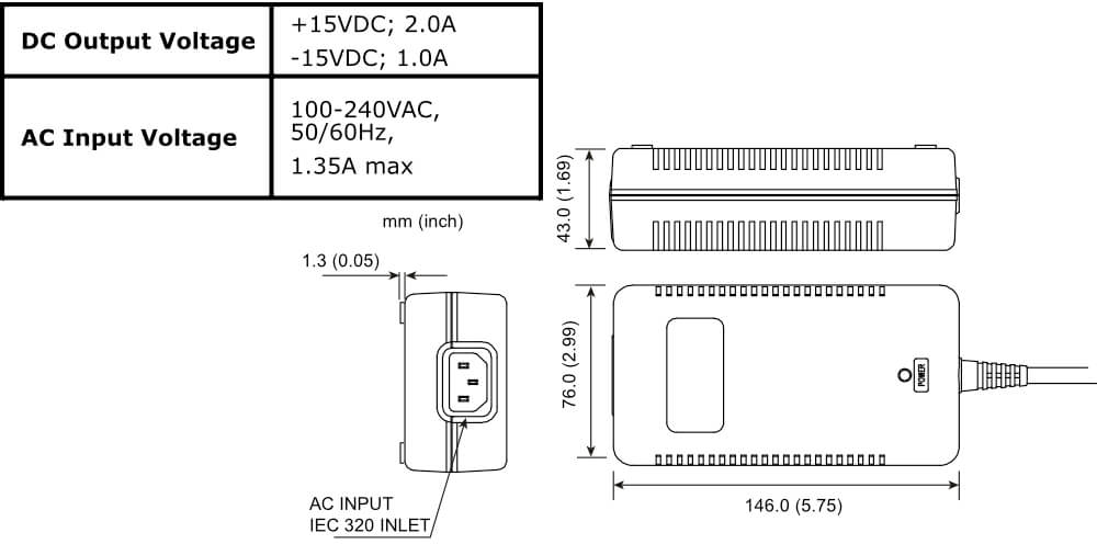
EXTERNAL POWER SUPPLY
EN191, EN192, and EN193 systems include an external power supply. The supply has a connector which allows direct connection to the enclosure.
This supply features a high-frequency (100kHz) switching supply. The high switching frequency allows the sensing modules to operate at maximum resolution.
 |