
USER’S MANUAL for the
SPINDLECHECK INSPECTOR
This instruction manual details the operation of the Lion Precision’s SpindleCheck Machine Capability Tester system with SpindleCheck Inspector Software. Please contact us if you have any questions or suggestions on how we can be of greater service to you.
Lion Precision
651-484-6544
info@lionprecision.com
www.spindlecheck.com
www.lionprecision.com
Manual Version:M017-7500.004
TABLE OF CONTENTS
- INTRODUCTION
- Measurements Performed by SpindleCheck
- SpindleCheck Components
- COMPONENT 1 – SPINDLECHECK DEVICE ELECTRONICS
- Probe Connections
- Index Sensor (Purple)
- Capacitive Displacement Sensors (X, Y, Z)
- COMPONENT 2 – CAPACITIVE PROBES (X, Y, Z)
- COMPONENT 3 – EDDY CURRENT PROBE (INDEX)
- COMPONENT 4 – PROBE SPACER
- COMPONENT 5 – PROBE NEST AND MAGNETIC BASE
- COMPONENT 6 – PRECISION TARGET PIN
- COMPONENT 7 – “ROUND” ADAPTER
- COMPONENT 8 – “ROUND WITH FLATS” ADAPTER
- COMPONENT 9 – FLASH DRIVE WITH SOFTWARE
- COMPONENT 10 – BATTERY & CHARGER
- COMPONENT 11 – GROUND BRUSH
- COMPONENT 12 – GROUNDING KIT
- SOFTWARE INSTALLATION
- Minimum Requirements
- Installation Procedure
- SOFTWARE BASICS
- Operating Mode
- Machine Selection
- Status Bar
- READING MEASUREMENT SCREENS
- Axis Names
- Initial Display
- Overall Results Area
- Chart Area Time/Sample/RPM
- Displayed Data
- Compare Data
- PREPARING TO MAKE MEASUREMENTS
- Power the SpindleCheck device
- Connect Device to Computer
- Launch SpindleCheck Inspector
- Confirm Settings
- Settings > Wireless
- Select a Machine (Machine Manager)
- Install the Target Pin
- Target Pins Care and Safety
- Install and Position Probes
- Measurement Types
- MAKING MEASUREMENTS
- Warm-Up
- POSITIONING CAPABILITY
- Vibration
- Repeatability
- Thermal
- Setup/Run
- CUTTING CAPABILITY
- Total Error
- Runout
- Roundness
- Roughness
- MEASUREMENT SEQUENCES
- Measure Machine Sequence
- Crash Test Sequence
- VIEWING REPORTS
- Printing and Viewing Options
- Machine: Machine Capability
- Machine: Machine Trends
- Shop Reports
- Appendix A: Replacement Parts
- GLOSSARY
- APPROVALS AND SAFETY CONSIDERATIONS
- Wireless System
- Battery
- Material Requirements
- Target Pins Care and Safety
- SOFTWARE LICENSE AGREEMENT
- Standards and References
- Assistance
INTRODUCTION
The SpindleCheck device is a precision measurement system for measuring the dynamic performance of machine tools and their spindles. SpindleCheck Inspector is a software package which retrieves and interprets the measurements from the SpindleCheck device and presents the results to the operator. The results inform the user about the capabilities of the machine.
Fundamental Concepts
SpindleCheck uses noncontact, capacitive sensors to measure error motions as changes in position of a precision target pin installed in the machine spindle.
The measurements are collected and analyzed by the SpindleCheck Inspector software. Measurement results are presented on-screen as changes over time or over different RPMs. Overall values are calculated and presented for the machine as a whole and for each axis.
Measurements Performed by SpindleCheck
SpindleCheck Inspector performs the following measurements as described in ISO, ANSI/ASME, and JIS standards:

SpindleCheck Components
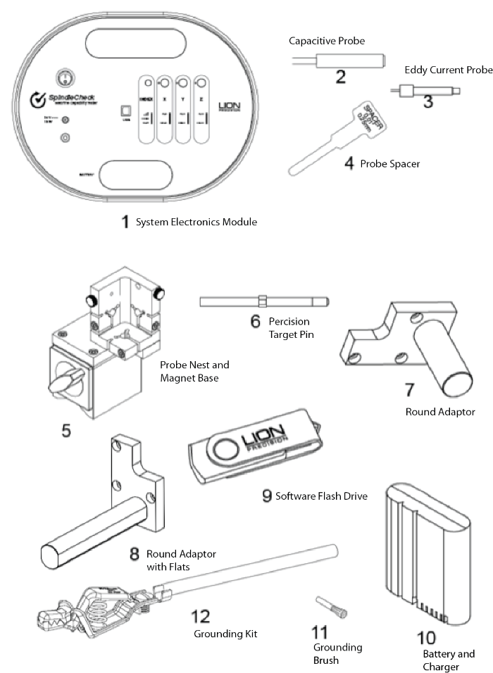
COMPONENT 1 – SPINDLECHECK DEVICE ELECTRONICS
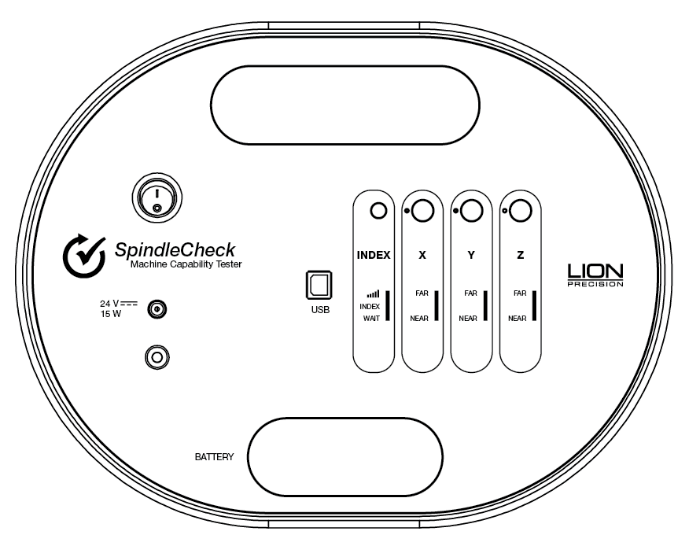
The sensor system electronics include driver electronics for the capacitive and index probes, an internal wireless router, a USB port for communicating with the PC, a battery slot, power and ground connections, a power switch, and probe position indicators useful during setup.
The rear of the device has four rubber feet and is magnetic for securing to a clean surface inside the machine.
Probe Connections
The Index sensor channel and X, Y, and Z capacitive displacement sensor channels are color coded. The colored blocks of each channel must match the color-coded rings on each probe.
Calibration stickers for each capacitive sensor channel (X, Y, and Z) are located on the back of the device. These indicate probe serial numbers and their association with particular channels.
 Index Sensor (Purple)
An index pulse is used to detect rotation. This signal is also used to align readings from multiple revolutions. The Index sensor uses an eddy current probe to detect the copper plating on the target pin.
The indicator lights provide feedback regarding the index function.
Signal Strength
The Index probe senses a difference between the copper and steel on the target. When the spindle is rotating, the resulting signal from the probe is used to time the measurements of the rotating spindle. The probe signal must be sufficiently large to ensure reliable triggers to the system. The closer the probe is to the target, the greater the signal strength, but the probe must maintain a safe distance from the rotating target to avoid contact. The PROBE SPACER is provided to set the ideal gap.
Signal Strength Indicator Conditions:
- Green: Good signal strength
- Red: Poor signal strength or no rotation
INDEX
This indicator lights Green when the Index probe is reading the copper strip and is Off when the Index probe is over the steel.
WAIT
The wait indicator lights during the 60-90 second initialization period when power is first applied to the SpindleCheck device. No communication between the computer and device is possible during this time.
 Capacitive Displacement Sensors (X, Y, Z)
The X, Y, and Z Axes each have a separate color-coded capacitive displacement sensor channel. The colored blocks of each channel must match the color-coded rings on each probe.
X: Blue
Y: Green
Z: Red
Indicator lights are Green when the probe is within its calibrated range.
The Near or Far light will be Red when the probe is outside of its calibrated range.
The Near and Far lights will be Blue when the capacitive probe is not connected.
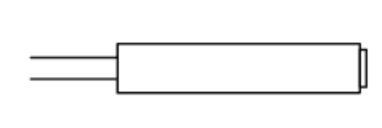 COMPONENT 2 – CAPACITIVE PROBES (X, Y, Z)
Noncontact capacitive probes measure the distance to the precision target pin as it turns. The probes are 8 mm in diameter, have a total measurment range of 0.250 mm (0.01 inch), and a minimum gap (Near Gap) of 0.125 mm (0.005 inch).
Calibration labels on the back of the electronics housing will list the specifics of the calibrations. If capacitive probes are damaged, the probe and the driver electronics for that channel must be replaced together to maintain accuracy.
Part Number P016-6002.
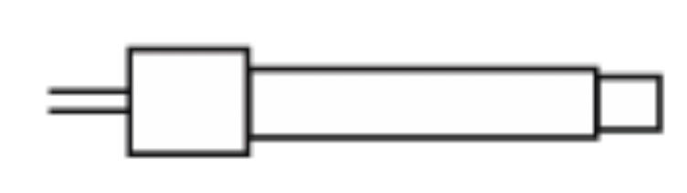 COMPONENT 3 – EDDY CURRENT PROBE (INDEX)
The eddy-current Index probe provides a once-around signal to align data for multiple rotations. Its nominal distance from the target is 0.25 mm (0.01 inch). Use cautionly to prevent damage.
Part Number P017-7070.
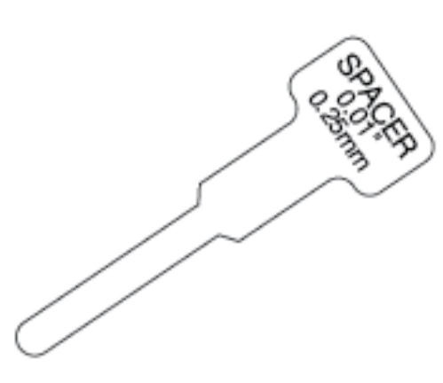 COMPONENT 4 – PROBE SPACER
The Probe Spacer is 0.25 mm (0.01 inch) thick and is used to set the gap between the probes and the target pin.
Part Number A017-7560.
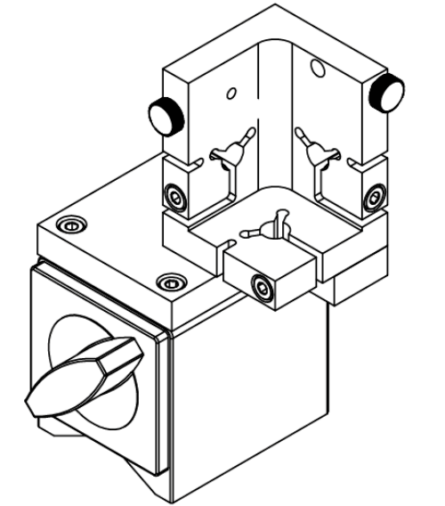 COMPONENT 5 – PROBE NEST AND MAGNETIC BASE
The probe nest includes mounting for X, Y, Z probes and an Index probe.
Part Number P017-6207.
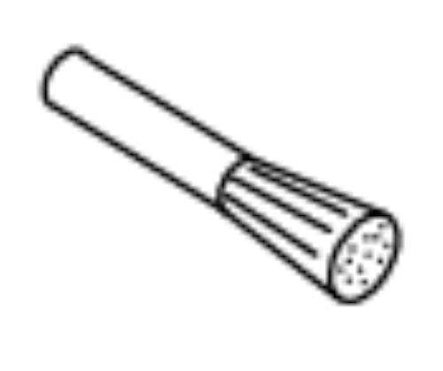
COMPONENT 6 – PRECISION TARGET PIN
A precision ground 8 mm pin is used as a target for measurements. The pin has a precision 1 inch (25.4 mm) diameter spherical end for Z-Axis measurements and a precision surface for measurements in the X and Y directions. The pin includes a collar with a copper plated area which is sensed by the Index probe.
The precision surfaces are important for accurate measurements. If these surfaces are damaged, the pin should be refinished by Lion Precision to restore an accurate reference
surface.
Part Numbers: 8mm pin – MFG5-1240 & 20mm pin – MFG5-1241.

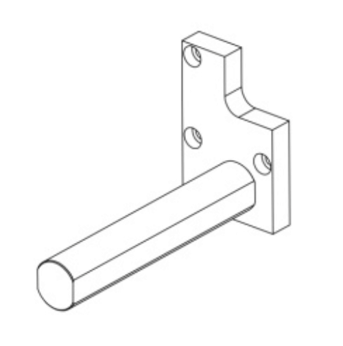
 COMPONENT 7 – “ROUND” ADAPTER
The Round Adapter mounts the probe nest to a cylindrical shank which can be mounted in the lathe turret. To use the adapter, remove the three screws holding the probe nest to the magnetic base. Remove the three screws holding the magnetic base adapter plate to the probe nest – use the same three screws to mount the probe nest to the adapter plate on the adapter.
Part Numbers: 1”- B017-3901 ; 1.25” – B017-3902 ;
20mm – B017-3905 ; 25mm – B017-3906 ; 3/4” B017-3900.
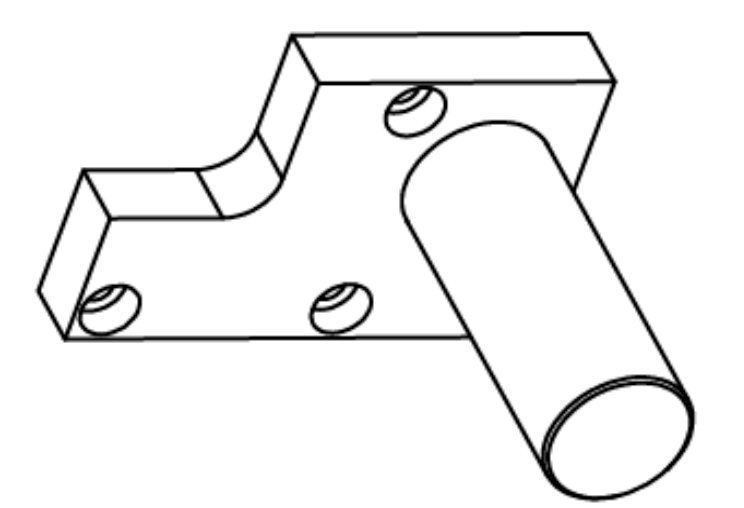
 COMPONENT 8 – “ROUND WITH FLATS” ADAPTER
The Round with Flats Adapter mounts the probe nest to a shank with two flats which can be mounted in the live tooling mount. To use the adapter, remove the three screws holding the probe nest to the magnetic base. Remove the three screws holding the magnetic base adapter plate to the probe nest – use the same three screws to mount the probe nest to the adapter plate on the adapter.
Part Numbers: 1” – B017-3911; 1.25” B017-3912;
3/4” – B017-3910.
 COMPONENT 9 – FLASH DRIVE WITH SOFTWARE
The 8G flash drive contains the SpindleCheck Inspector software. See software on page 12 for installation details.
 COMPONENT 10 – BATTERY & CHARGER
The 15VDC battery is a lithium-ion type. Two are provided with each system. The battery housing is polarized and will only insert in the SpindleCheck device one way. The battery lasts about four hours and requires about five hours to fully charge.
System also comes with a battery charger.
Part Number P017-7570 and 2901-0060 (Charger)
 COMPONENT 11 – GROUND BRUSH
The Ground Brush can be fastened into the probe nest and the carbon fiber brush used to ground the target pin while spinning. This is usually not necessary but can be helpful in an electrically noisy environment. If readings are erratic or the Roughness measurement unusually high, the ground brush may be necessary.
Part Number P017-4351.
COMPONENT 12 – GROUNDING KIT
Grounding the SpindleCheck device to the spindle housing may be necessary to reduce electrical noise from the machine’s environment. The ground strap includes a “banana” plug to connect to the SpindleCheck ground connector and a clamp to connect to a convenient point on the spindle housing.
Part Number P014-8250.
SOFTWARE INSTALLATION
Minimum Requirements
Note .NET3.5 must be installed before running SpindleCheck Inspector installation.
- Windows 8 or higher (64 bit)
- 8G memory
- 64G free disk space
- 1 GHz Processor
- 1 Available USB port (2.0 or higher); 1024 x 768 Minimum Screen Resolution
Installation Procedure
The SpindleCheck Inspector program is installed in the \Program Files (x86)\Lion Precision\Spindle Check Inspector directory on your hard disk. If you install the SpindleCheck
Inspector software a second time using the same subdirectory, the previous installation will automatically be uninstalled first.
To use the SpindleCheck Inspector flash drive:
1. Ensure you have a good internet connection.
2. Insert the Lion Precision SpindleCheck Inspector flash drive in available USB port.
3. View the contents of the flash drive.
4. Run SpindleCheckInspectorInstall.exe
5. Follow the directions of the installation programs.
6. When the installation is done, restart the computer.
7. After restarting, run the program by selecting the icon on the desktop, or by selecting Start > All Programs > SpindleCheck Inspector > SpindleCheck Inspector.exe
SOFTWARE BASICS
Operating Mode
When the SpindleCheck Inspector is launched (Start > SpindleCheck Inspector) it will try to connect to a SpindleCheck device. If it is successful, the Home Screen will be displayed.
If it does not find a connection to a SpindleCheck device, you will be given the option to Retry the connection, or to View Data previously collected.
More details in the Launch SpindleCheck Inspector section.
Machine Selection
To make measurements, SpindleCheck Inspector requires a SpindleCheck device to be connected and a machine to be loaded from the database. When a device is not connected and/or a machine is not loaded, Home Screen measurement buttons will be deactivated (grayed out).
More details in Select a Machine (Machine Manager).
Status Bar
The Status Bar at the bottom of the screen displays the following information:
• SpindleCheck Inspector software version
• Connection to device status:
▪ Device Connected
• Rotation status:
▪ Spinning
• Current RPM
• Constant Error/Unstable
• Currently selected pin size. Accurate measurements require the correct pin size be selected.
READING MEASUREMENT SCREENS
Axis Names
Some measurements read each axis separately (Warm-Up, Vibration, Repeatability, Thermal, Runout, Position Shift) and report results for the X, Y, and Z axes. Other measurements read the “radial” axis as a mathematical combination of X and Y (Total Error, Roundness, Roughness) and report results for the Radial and Axial axes.
Initial Display
When a measurement screen is first displayed it will show the most recent results of that measurement for the current machine. At the conclusion of a new test run, the screen will display the just completed test results.
Overall Results Area
Values
The Overall Results Area contains measurement values intended to give an overall picture of the machine and each axis. “Axis Averages” indicate the condition of individual axes. The “Combined” value represents the machine overall. The Combined value is always larger than the values for individual axes.
Pass/Fail
If Pass/Fail numbers are entered into the Machine Manager > Pass/Fail, the Combined result will be compared to the Pass/Fail number. If no number has been entered in the Pass/Fail screen, a Pass/Fail test will not be performed.
Best/Worst RPM
For measurements taken across a range of spindle speeds, this area lists the best and worst performing speeds for each axis.
Notes
Notes regarding the currently displayed measurement can be entered or edited at any time. Clicking in the Notes text box will allow you to type or edit with the usual Windows text functions. Use the “Save” button to save your notes.
Chart Area Time/Sample/RPM
The chart area of each screen displays a table of the measurements at each test condition (RPM, Time, or Sample). Moving the cursor over the chart will display the individual values at each point on the table.
Displayed Data
The Screen displays the most recent measurement results for the current machine. To view an earlier measurement of the machine, use the “Displayed Data” drop down to select a different Date/Time/Type record to display. The Chart Area and Overall Results Area will display the
selected record.
Compare Data
In the Chart Area, you can also compare two different sets of measurements for the same machine. Select another Date/Time/Type record from the Compare Data dropdown. The chart will simultaneously display the Compare Data with dashed lines. The Overall Results Section will continue to display the Displayed Data information.
The Notes section can be selected to show Display data or Compare data with the buttons under the Notes textbox.
PREPARING TO MAKE MEASUREMENTS
The process of making measurements follows this basic sequence:
1. Power the SpindleCheck device
2. Connect the device to the computer
3. Launch SpindleCheck Inspector software
4. Confirm settings
5. Load or create the machine to be measured from the machine database
6. Install the target pin in the spindle
7. Install and position the measurement probes
Power the SpindleCheck device
Insert a battery into the SpindleCheck (or connect to power supply) and turn the power switch on. The NOT READY light will be on (Index channel) for about 90 seconds. During this time, no communication is possible with the device.
Connect Device to Computer
Option A – Connect through WiFi Network
1. Select the Network icon in the notification area on your computer.
2. In the list of networks, choose “SpindleCheck” to connect to, and then select Connect. We recommended you to check the “Connect Automatically”.

3. Type the security key (often called the password), “LionPrecision” and then click Next. Why isn’t this called a “password”?
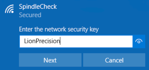
4. >… Select “Home network” and it might need a few minutes to setup.
5. When the WiFi is successfully connected, the Network or icon will show like this .
Change wireless SSID and Password please refer to Settings > Wireless
 Option B – Connect through USB
1. Plug in the USB cable – TypeB to SpindleCheck Inspector and the other end USB – TypeA to the host computer.
2. This might take a few minutes for the computer to recognize and install the driver.
3. Check to see if a device name called “Microsoft Windows Mobile Remote Adapter #xx” or “CompactFlex” is active.
Launch SpindleCheck Inspector
When the SpindleCheck Inspector is launched (Start > SpindleCheck Inspector ) it will try to connect to a SpindleCheck device. If it is successful, the Home Screen will be displayed. If it does not find a connection to a SpindleCheck device, you will be given the option to Retry the connection, or to View Data previously collected.
“Retry”
1. Confirm the SpindleCheck device is turned on and its Not Ready light is off.
2. Confirm that the computer is connected to the SpindleCheck wireless network or connected by USB cable.
3. Then Retry.
Home Screen
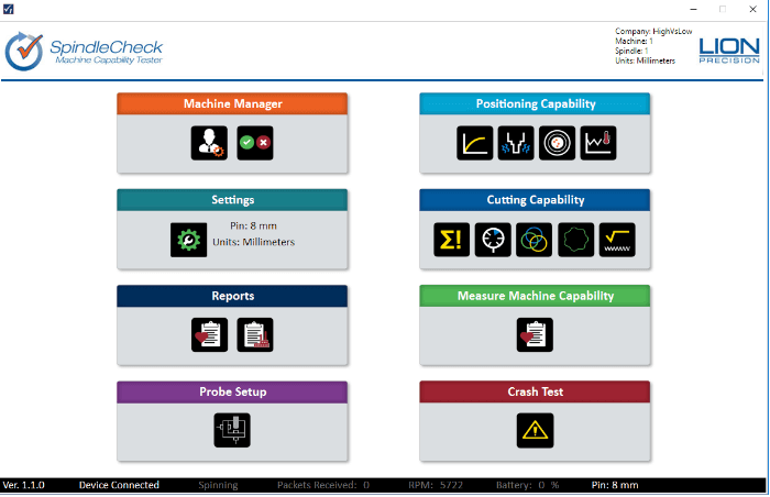
The Home Screen of SpindleCheck Inspector contains eight buttons to access different functions. When first launched, some of the buttons will be grayed out as they have no function until a particular machine is specified. When a machine has been loaded, the machine description will be listed in the top right corner next to the Lion Precision logo. If you are going to measure a machine, the first step is loading a machine in the Machine Manager.
Confirm Settings
Settings > Configuration
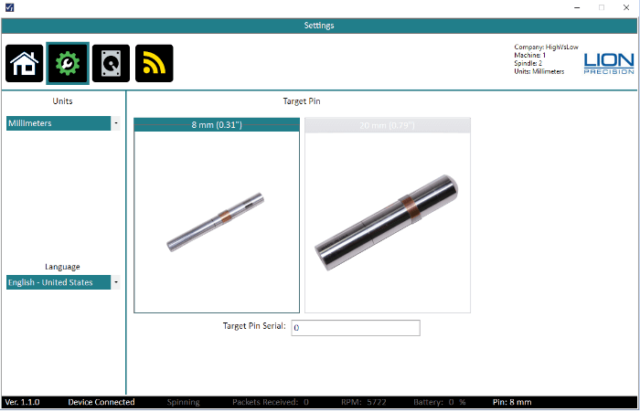
Units
Choose inch or mm for display. The units can be changed anytime.
Target Pin
The noncontact sensors measure changes in distance between the sensor and the Target Pin placed in the axis of rotation of the machine. The Target Pins are designed with a precise diameter and minimal roundness error.
The SpindleCheck system must know the size of the Target Pin to make precise calculations during measurements. Be certain to select the correct pin size you are using during your measurement.
Target Pin Serial
This is an optional entry.
Target Pins are marked with serial numbers. The Target Pin serial number is recorded with each measurement to support traceability.
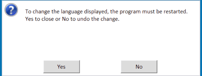
Language
Select your desired language and a message box will popup to confirm the action. After clicking “Yes” the program will shut down, and the user will need to restart the program, if clicking “No”, the language field changes back to previous language, no restart is necessary.
Settings > System Data
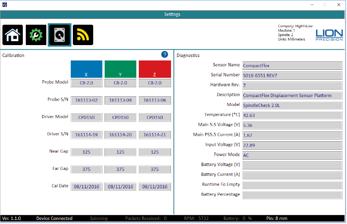
Calibration
The Calibration section lists the specific probe and electronic component serial numbers, and Near gap and Far gap for each measurement channel. It also lists the date of the last calibration of the system.
WARNING: IF A PROBE IS VISIBLY DAMAGED, accuracy will be affected. The probe and its driver electronics should be replaced.
Diagnostics
The Diagnostics section lists data relative to the inner workings of the software and the electronics. These values may be needed by Lion Precision engineers to troubleshoot the system in the unlikely event that there is a problem.
Settings > Wireless
This Wireless Panel is for the user to change/update the wireless network name (SSID) and Wireless Password.
• Make sure device is connected through WiFi network.
• Current Password – Will show you the previous changed password by using this PC.
• All text boxes must be entered. If one of them is empty, software will prompt warning.
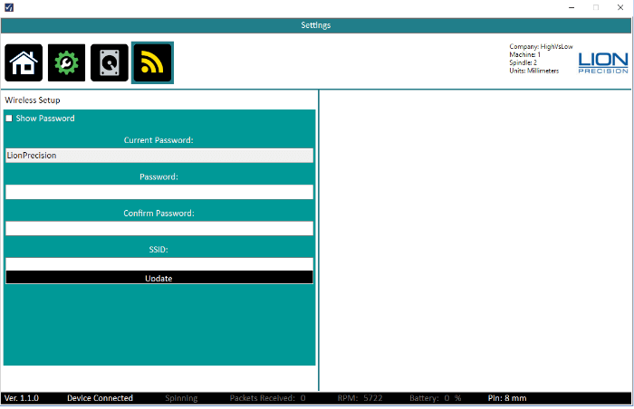
WARNING: Password and Confirm Password – Must be longer than 8 characters and both inputs must match or else the software will prompt warning.
There is a “Show Password” Checkbox. User can check it and both Password and Confirm Password textbox will show the password.
• SSID – Desire name for the wireless broadcast.
• Click the Update button and the software will update the router with the new password and SSID on the router.
• A message box will prompt when the router is successfully updated. The user will be dropped off from the current connection and require reconnecting with the updated network password.
Select a Machine (Machine Manager)
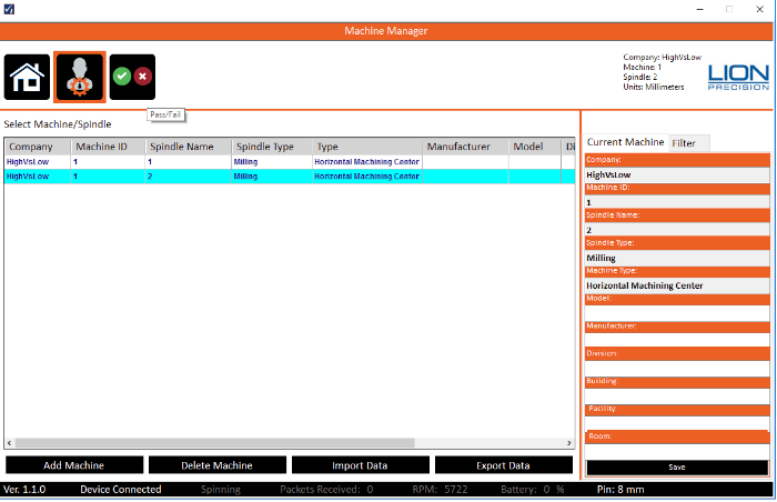
SpindleCheck Inspector contains a database of machines/spindles and their measurements, because some machines have multiple spindles, the machine AND spindle must be identified. No measurement can be made unless a specific machine and spindle have been selected. The following data is required for each machine:
- Company: The company who owns the machine
- Machine ID: A unique identifier for the machine within the company. This is often taken from an asset tag or similar identifier. No two machines from the same company can have the same Machine ID.
- Machine Type:
- Vertical Machining Center
- Horizontal Machining Center
- Turning Center
- Sliding Head Machine (Swiss)
- Multi-Task Machine
- Lathe
- Spindle Name: Identify the spindle to be measured
- Spindle Type: Milling or Turning. Measurement values within SpindleCheck Inspector are calculated differently depending on the spindle type.
NOTE: If Company, Machine ID, Machine Type, Spindle Name, and Spindle Type are not loaded properly the new machine will not save.
Additionally, other information such as the machine’s specific location can also be included in the machine description.
Load an Existing Machine
To load an existing machine simply select and click from the list.
Filter
A “Filter” tab on the right side of the screen allows you to filter on many of the fields – just type in a text field or select from a drop down and the list will filter accordingly.
Create New Machine
To create a new machine, click the New Machine button. A popup dialog will require five pieces of information (listed above) to describe the new machine. Click Done to create the machine. The dialog will close and the new machine will be loaded. More detail can be added to the new machine in the fields on the right side of the screen.
Import/Export Data
Machines and their measurements can be exported and imported as required to share machine information between more than one installation of SpindleCheck Inspector.
Export Data
A single machine (and all of its spindles) or an entire filtered list can be exported. When exporting, you will be asked to identify a location to save a *.smmx file. This is the file which will be selected for import into another installation of SpindleCheck Inspector.
To identify a single machine to export, select it in the list (highlighted text).
To export a group of machines, use the filter functions to create the desired list on screen.
Click Export Data and select Single Machine Selected or Current Filtered List in the dialog. Select the location for the *.smmx file.
Import Data
Click Import Data button. Use the file selection popup to navigate to the desired *.smmx file and select the file. The data in the file is imported into the local database.
Pass/Fail
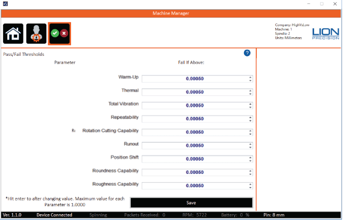
Each measurement available in SpindleCheck Inspector can have a Pass/Fail threshold.
If no value or “0’ is entered, the Pass/Fail test will not be performed.
Install the Target Pin
Target pins (8 mm diameter standard, 20 mm optional) are to be installed in the tool/part holder of the spindle to be measured. The etched line on the pin marks the depth of insertion into the collet.
Target Pins Care and Safety
The precision target pin has a maximum rotational speed of 120,000 RPM. Highspeed rotation can create substantial energy. Care must be taken to protect operators when rotating parts at high speeds. Guarding is recommended. Positioning the probe nest such that it is between the operator and the spinning target will provide some degree of protection.
The target pins are high precision components that require special care similar to gauge blocks. Avoid touching the measurement end of the pin and be careful not to crash the pin during operation. Crashing the pin into the probe could damage both the pin and the probe.
Install and Position Probes
There are five goals in the mechanical setup:
Probes never make contact with target during rotation (incidental contact during setup while the spindle is not rotating is safe)
Target pin axis is aligned with Z probe axis (pin’s spherical end is centered on the probe)
Probes are adjusted to the center of their measurement ranges
Probes stay in range during the full rotation of the spindle
Index probe is properly spaced from the copper target area of the pin
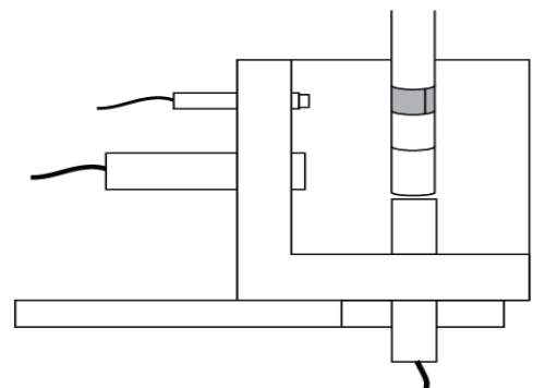
Install Probes in the Probe Nest
Loosen the probe clamp screws and install the probes in the nest so they protrude a small amount into the target pin area. Tighten the probe clamps slightly so that the probes are held in place but can still be repositioned by hand.
WARNING: DO NOT PULL ON PROBE CABLES
Mount the probe nest magnetic base such that the target pin can be moved into range of the
probes in the nest. Align the X-axis probe (blue) and the Y-axis probe (green) with their
respective axes. Switch the magnet on and verify it is firmly in place.
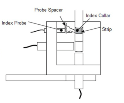
 Initial Positioning Spindle/Targets and Probes
Move the machine axes so that the pin is approximately centered over the Z probe and the collar on the pin is approximately centered with the index probe.
 Go to Probe Setup function on SpindleCheck Inspector.
Adjust X and Y axes as necessary to center the pin over the Z-axis probe.
Adjust the Z axis until the X and Y probes are approximately centered on the finished surface at the end of the pin and the Index Probe is aligned to the Index Collar.
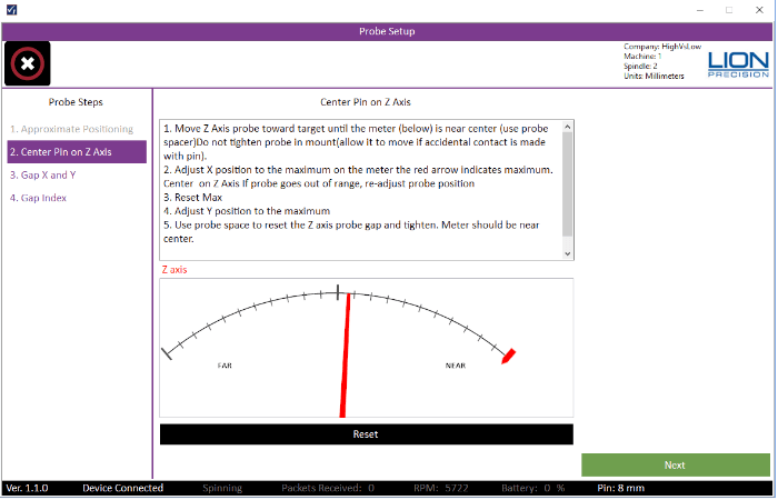
Final Positioning of Spindle/Target and Z Probe
Move the Z-axis probe toward the target pin and place the Probe Spacer between the probe and end of the target pin. Tighten the probe set-screw and remove spacer.
On screen, click Next to get to the Center Pin on Z Axis step.
To precisely center, adjust X and Y to find the “high-spot” of the end of the pin. The meter on the screen includes a small red marker that indicates the high spot. Scan across the X axis until it is at the high spot, then click Reset Max and scan the Y axis until it as at the high spot.
Use the probe spacer and move the Z-axis probe to set the gap between the target pin and probe. After removing the spacer, the on-screen indicator should be near the center of the meter display (pointing in a vertical direction) and the Zaxis range lights on the SpindleCheck device
should be green.
Tighten the Z-axis probe. Click Next on screen.
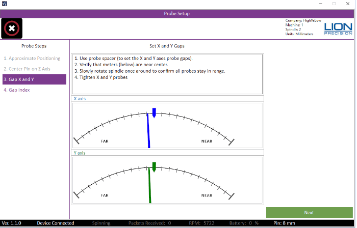
Final Positioning of X- and Y-Axis Probes
Use the Probe Spacer and move the X, Y probes to set the gap between the probes and target pin. After removing the spacer, the X- and Y-Axis indicators should be near the center of the meter displays (pointing up) and their range indicators on the SpindleCheck device should be green. Rotate the spindle once by hand and verify that the lights on the device stay green through the entire rotation. Click Next on screen.
Final Positioning of index Probe
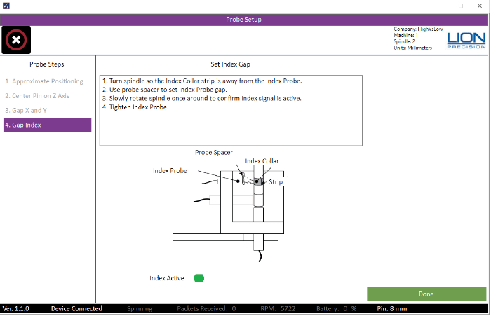
Turn spindle so the Index Collar strip is away from the Index Probe. Use probe spacer to set Index Probe gap. Slowly rotate spindle once around to confirm Index signal is active then tighten Index Probe.
Click Done on screen.
MAKING MEASUREMENTS
Measurements can be made individually, or the Measure Machine Sequence or Crash Test Sequence can guide you quickly through an entire machine measurement.
Measurement Types
Reports and on-screen displays can be filtered by the measurement type. Measurements can be saved as one of three different types:
- Maintenance
- Measurements made on a periodic basis to track the machine’s performance over time.
- Troubleshooting
- Measurements made while changing conditions in an effort to solve a problem. This often results in multiple measurements over a short period of time.
- Crash
- Measurements made after a machine crash to determine if the machine’s capabilities have changed.
POSITIONING CAPABILITY
Warm-Up
Related Standards:
ISO 230-3, 6
- ASME B5.54, B5.57, 7.6.2.1, 7.7.2.1
Process:
1. Start with a ‘cold’ spindle (minimum 12 hours of no operation before beginning test).
2. Select a duration (10-120 minutes)
3. Start the spindle turning at 75% of maximum.
4. Begin the test.
The measurement will not run if the spindle is not rotating.
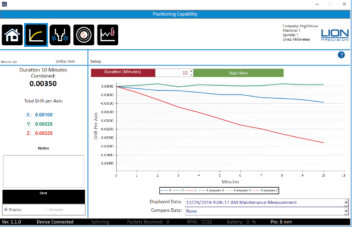
Description:
Measure the position of the target pin in all three axes. The first reading is set as the zero/ reference for the rest of the test. After the initial reading, position readings are taken every minute and plotted on the chart. Multiple samples per revolution for 32 revolutions are averaged to find the static location of the spindle.
At the conclusion of the test, the total range (maximum – minimum) for each axis is calculated and presented as Total Drift per Axis.
The Combined Drift for the machine is the square root of the sum of squares of the individual Total Drift values. To generate a single Combined Drift value for the machine: √X2 + Y2 + Z2 . Note that the Combined value is always larger than any individual value.
Purpose:
When a cold spindle begins to rotate, friction-heating of the bearings causes the spindle to expand, primarily in the Z axis. Knowing the time until a machine stabilizes allows for more precise scheduling/planning of machine time, less scrap, and may reveal unexpected machineframe distortions and problems with thermal compensation or problems with spindle chiller settings
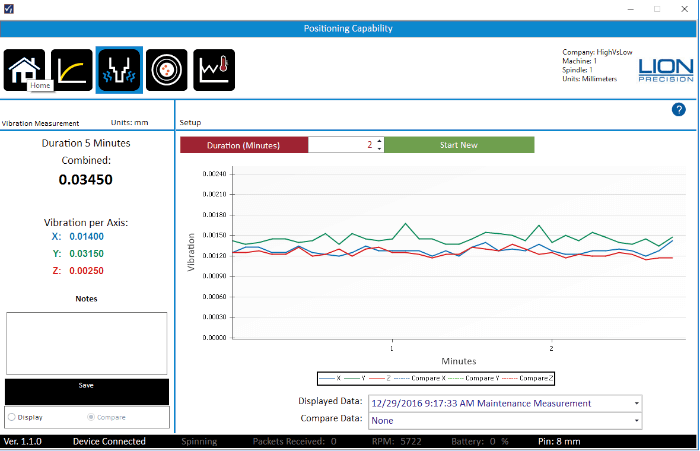
Vibration
Related Standards:
ISO 230-3, 6
- ISO 230-7, 5.3;
- ASME B5.54, 5.57, 6.3
Process:
1. Select a time duration for the vibration test 1-10 minutes (standards require 10 minutes)
2. Spindle must not be turning
3. Start the test
4. Note any unusual disturbances correlating to spikes in the vibration measurement (forklifts, CNC punches etc.)
Description:
The probes measure vibration in all three axes while spindle is not turning. According to international standards, the vibration value is “the maximum range of the displacement” during any 5 second period during the time of the test.
Measurements are taken at over 1,000 samples/second (as required by standards). Every five seconds the maximum range (peak to valley) value is calculated for that 5 second interval for each axis and plotted on the chart. When the test duration is completed, the highest value on the chart is the Vibration for that axis.
The Combined Vibration for the machine is the square root of the sum of squares of the individual Vibration values: √X² + Y² + Z². Note that the Combined value is always larger than any individual value.
Standards describe different types of vibration:
Seismic Vibration: The vibration coupled into a machine through the floor from the surrounding environment.
Relative Vibration: Vibration between the “tool-holding part of the machine and workpieceholding part of the machine.”
Standards recommend vibration measurements taken with the machine “off” and with the machine “on” but not rotating. This will reveal additional vibration added when pumps and servos are activated.
Purpose:
Constant vibration is primarily related to surface finish capabilities of the machine. As the part is being cut, the tool is moving according to the vibration leaving some remnant of the vibration pattern on the part’s surface. Impulse or Shock type vibration from a fork lift or similar can cause a part to fail if it occurs during a critical cut.
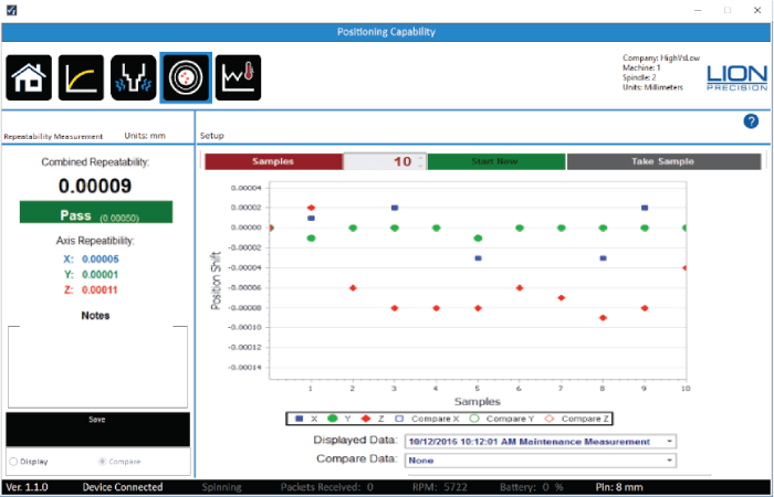
Repeatability
Related Standards:
- ISO 230-2,
- ASME B5.54, 7.3; B5.57, 8.4
Process:
- Test requires a non-rotating spindle
- Set the number of samples (3-10; standards require 10)
- Position the spindle and setup probes
- Start test to take initial measurement. This position of the spindle will be the reference point for all other samples.
- BEING CAREFUL TO AVOID CRASHING INTO PROBES – Move the spindle to other locations and return to initial location.
- Take Sample.
- Repeat steps 5 and 6 until the test is complete.
Description:
After establishing an initial position as a reference, the spindle/table is moved and returned the initial position. Another measurement sample is taken and the change in position for each axis is plotted on the chart. This is repeated for the number samples set for the test (standards require 10). The final repeatability value of each axis is the range of measurements (max-min) on the plot for that axis. The Combined Repeatability for the machine is the square root of the sum of squares of the individual repeatability values: √X² + Y² + Z². Note that the Combined value is always larger than any individual value.
Purpose:
This test determines the machine’s ability to move the spindle (and/or table) and return to the initial position. As the mechanics of the machine wear, backlash and other issues will reduce the machine’s ability to accurately locate the cutting tool relative the workpiece. The measurement allows some prediction of the machine’s ability to hold tolerance for feature location. Troubleshooting a feature location problem is simplified when it can easily be determined which axis has the problem. If the machine’s axes are exercised between samples, thermal drift caused by the heating of the mechanical elements (ball screws) of the axes can be determined.
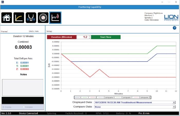
Thermal
Process:
While the Thermal measurement operates the same as the Warm-up measurement, it is for troubleshooting and experimenting. There is no set process. Begin to take measurements (spindle can be turning, but does not have to be turning) and change thermal variables to see if it affects the spindle position.
Description:
Measure the position of the target pin in all three axes. The first reading is set as the zero/ reference for the rest of the test. After the initial reading, position readings are taken every minute and plotted on the chart.
If the spindle is rotating, multiple samples per revolution are taken for 32 revolutions are averaged to find the static location of the spindle. At the conclusion of the test, the total range (maximum – minimum) for each axis is calculated and presented as Total Drift per Axis.
The Combined Drift for the machine is the square root of the sum of squares of the individual Total Drift values: √X² + Y² + Z². Note that the Combined value is always larger than any
individual value.
Purpose:
Change in room temperature or changes in chiller settings are examples of the sort of troubleshooting tests that can be done with this measurement.
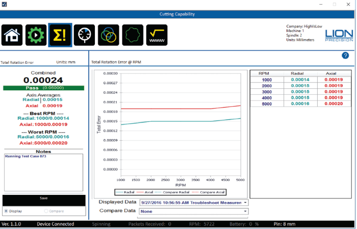
CUTTING CAPABILITY
Setup/Run
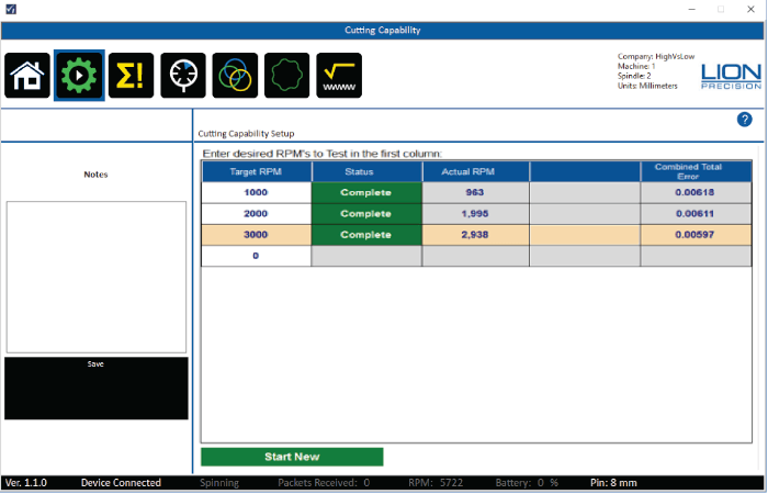
Cutting Capability simultaneously measures the following parameters of the machine at selected spindle speeds:
• Total Rotational Error
• Runout
• Position Change
• Roundness Capability
• Roughness Capability
Each of those measurements is discussed in their own section of the manual and help screens.
Process:
- Enter up to 50 Target RPMs in the table. Each speed must be at least 5% different than the next closest speed. It is advised to go from slowest to fastest (Click the top of the RPM column to sort the column if necessary).
- Start spindle at the first listed speed
- Click the Start Cutting Capabilities Button (spindle must be rotating)
- The first Target RPM indicator will display “Seeking” as it waits for the spindle to come to speed
- When SpindleCheck measures a stable RPM within 5% of the Target the indicator will change to “Measuring”
- The measurements are taken and the indicator changed to “Complete”
- The Combined Total Error at the RPM is displayed
- The next Target RPM indicator changes to “Seeking”
- Change spindle speed to the next Target RPM and wait for the measurement to be taken. Time to stabilize and measure can vary based on the RPM of the spindle.
- Repeat for each Target RPM
- Should there be any concerns about the measurement just taken (i.e. forklift drives by), leave the spindle at the same speed and click the “Redo” button after the measurement is complete.
“Forcing” a Measurement
If the spindle speed setting on the machine produces an actual speed which is off by more than 5%, SpindleCheck will not take the measurement. Clicking the “Force” button will force SpindleCheck to take the measurement at the current speed.
Description:
When a stable Target RPM is detected, SpindleCheck takes multiple measurements per revolution for 32 revolutions. These measurements are used in the calculations of all the values in the Cutting Capabilities tests.
Purpose:
All of the measurements in the Cutting Capabilities are about the accuracy of rotation. A perfect condition would mean that the center of the axis of rotation is perfectly stationary while rotating. Unfortunately, when examined closely enough, the axis of rotation is never perfectly stationary during the rotation. Any deviation of the axis of rotation is an “error motion.”
There are different types of error motions. Each type contributes to a different type of problem in the finished part (roundness, feature location, hole size, surface roughness). Each of the measurements in the cutting capabilities section measures a different type of error motion relating to a different type of effect on the machined part.
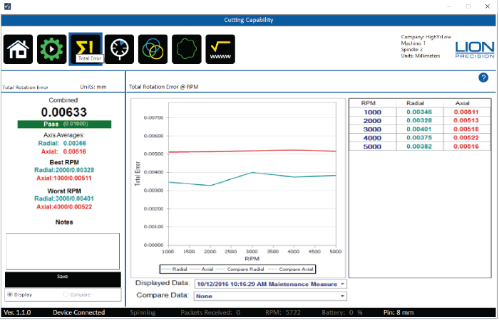
Total Error
Related Standards:
- ASME B89.3.4
- Turning: ISO 230-7, 5.5; ASME B5.57, 7.5.3;
- Milling: ISO 230-7, 5.4; ASME B5.54, 7.5.3; ASME B5.57, 7.6.4
Description:
Essentially, the Total Rotation Error is the measurement of the size of the envelope in which the axis rotates. It describes the total range of possible positions of a tool at any angle of rotation.
Total Rotation Error is measured on two axes, Radial and Axial. The Axial measurement is a measurement in the Z axis. The Radial measurement depends on whether it is measuring a turning spindle or milling spindle. If a milling spindle, the Radial axis is a mathematical combination the X and Y axes which the standards call a “rotating sensitive direction” measurement. In a turning spindle the Radial axis is the X axis which the standards call a “fixed sensitive direction” measurement.
The Axis Averages are averages across all spindle speeds for each axis.
The Combined Total Error for the machine is the square root of the sum of squares of the individual Total Error values: √Radial² + Axial². Note that the Combined value is always larger
than any individual value.
Purpose:
Individual components of the “Total Rotation Error” provide insight into specific part errors; the Total Rotation Error (total error motion) provides a measurement of the general condition of the axis of rotation. The Combined Total Rotation Error is good for a quick comparison of the condition of multiple machines or the trends for a particular machine.
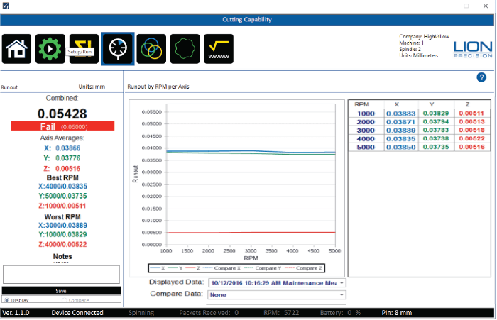
Runout

Description:
Runout is the Total Indicator Reading (TIR) of the surface of the target pin during rotation. As the pin turns, the maximum and minimum distance between the pin and the probe in each axis is recorded. The difference (Max-Min) is the Runout.
Runout is measured in each axis. The Combined Runout for the machine is the square root of the sum of squares of the individual Runout values: √X² + Y² + Z². Note that the Combined value is always larger than any individual value. Runout measurement includes the centering and roundness errors of the collet, tool holder, taper, and the target pin itself. Because of these errors, runout is not a good indication of the condition of the rotary axis. A rotary axis that turns nearly perfectly could produce a large amount of runout due to bent parts, chips in the tool holder or many other sources. Because these errors in the tool holder, taper, and collet are additive, runout can be changed by simply rotating the tool holder 180°.
Purpose:
Runout is a common measurement in the machine tool industry. Runout will affect the diameter
of holes and straightness of straight cuts. It should not change dramatically with changes in
speed. If it does, it could be a sign of significant wear causing the system to shift or bend as the
spindle turns faster.

Related Standards:
- ASME B89.3.4, 2.7.11
Description:
Position Shift measures the static location of the spindle at different spindle speeds. The total shift for each axis is the Maximum-Minimum of the values charted for that axis. The Combined Shift for the machine is the square root of the sum of squares of the individual Shift values: √X² + Y² + Z² . Note that the Combined value is always larger than any individual value.
Purpose:
Large position shifts between speeds indicate significant bearing wear or a lack of stiffness in the machine.
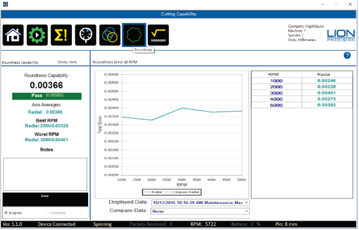
Roundness
Related Standards:
- ▪ Turning: ISO 230-7, 5.5; ASME B5.57, 7.5.3
- ▪ Milling: ISO 230-7, 5.4; ASME B5.54, 7.5.3; ASME B5.57, 7.6.4
Description:
Roundness Capability describes the ability of the machine to create round features when drilling or boring with a milling type spindle, or any radial cutting on a lathe type spindle. The measurement of Roundness Capability is an accurate prediction of the roundness of features formed in this way. It does not apply to round features created by moving the workpiece/spindle in a circle on a mill.
Roundness Capability is only measured on the Radial axis. The calculation of the Radial axis measurement depends on whether it is a turning spindle or milling spindle. If a milling spindle, the Radial axis is a mathematical combination the X and Y axes which the standards call “rotating sensitive direction.” If a turning spindle, the Radial axis is the X axis which the standards call “fixed sensitive direction.”
The Radial result is the average of the values at each speed. Because there is only one axis measured for Roundness Capability (the radial axis), the Combined Roundness Capability for the machine is equal to the Radial axis measurement.
Purpose:
As an accurate predictor, the Roundness Capability value can be used to determine a machine’s ability to reliably produce part features with a specified roundness.
Roughness
Related Standards:
- ASME: B89-3-4, A-7.3
- Turning: ISO 230-7, 5.5; ASME B5.57, 7.5.3
- Milling: ISO 230-7, 5.4; ASME B5.54, 7.5.3; ASME B5.57, 7.6.4
Description:
Surface Roughness Capability is based on measurements of the “asynchronous” error motions of the spindle. According to ASME B89.3.4 (and similar standards), “asynchronous error motion is the portion of total error motion that occurs at frequencies other than integer multiples of the rotation frequency.” These are caused by machine vibrations and imperfections in the spindle’s roller bearing components.
The Axis Averages are the average across all spindle speeds for each axis.
The Combined Roughness Capability for the machine is the square root of the sum of squares of the individual Roughness values: Radial² + Axial². Note that the Combined value is always larger than any individual value.
Purpose:
Surface roughness is the result of a very complex relationship of many factors. One of them is the asynchronous error motions of the spindle (B89-3-4; A-7.3). In ideal cutting conditions with a single-point tool the Surface Roughness Capability would be a reasonable prediction of the surface roughness (Ra) of the finished surface. But cutting conditions are never ideal and multipoint tools are in use much more often.
The Surface Roughness Capability provides a comparison between machines for roughness performance, and it provides a potential best-case limit to what roughness the machine is capable, as well as indicating which spindle speeds offer the best and worst performance.
MEASUREMENT SEQUENCES
To make machine measurement faster and easier, two Measurement Sequences are available, Measure Machine Sequence and Crash Test Sequence.
A sequence guides the user through a series of measurements from just one screen. The user simply clicks the Next button after each measurement. To skip a test, just click Next without performing the test.
A list of the sequence steps is tracked on the left side of the screen allowing the user to see where the process is and if any steps have been skipped.
If the probes are not in their operating range, the system will assume the probes have not yet been positioned and will begin with a probe setup process.
The sequence can be “Canceled” at any time with the button at the top left, but any completed measurements will remain in the database.
Measure Machine Sequence
The Measure Machine Sequence is used for periodic measurements of the machine and ends with a Machine Capability Report. The measurements in the sequence include:
- Probe Setup
- Warm-Up
- Vibration
- Repeatability
- Cutting Capabilities
- Machine Capability Report
- Crash Test Sequence
The Crash Test Sequence is used to confirm a machine’s condition after a crash and ends with a Machine Trend Report showing the machine’s history and its performance after the crash. The measurements in the sequence include:
- Probe Setup
- Vibration
- Repeatability
- Cutting Capabilities
- Machine Trend Report
VIEWING REPORTS
Several reports are available in SpindleCheck Inspector. These reports make it easy to understand a machine’s capabilities, strengths, weaknesses, and general condition. Armed with this information, everyone can know the best and worst speeds for different operations, how the machine performs while warming up, if periodic maintenance is required and more.
Reports can be viewed without being connected to a SpindleCheck device.
Printing and Viewing Options
Reports which are displayed in a report viewer on screen from which the report can be printed or exported as PDF, Excel, or MS Word documents.
The report viewer has a tool bar across the top with several options described below.
- Click the report icon to generate a report which displays in a new window.
- Click the Printer icon to print the report.
- Click the “Save As/Export” icon at the right of the top menu bar to export as PDF, MS Word doc, or Excel file.
Machine: Machine Capability
The Machine Capability Report is the summation of what is known about the machine’s current capability. It presents the most recent Maintenance Measurement results for the currently loaded machine. Only Maintenance type measurements are shown on this report.
Separate sections display the results for each of the available measurements in SpindleCheck.
If a particular measurement has never been taken on a machine, the section will display NO DATA.
With a machine capability report, operators, programmers, and management can quickly understand the machine’s best and worst performing characteristics. This helps in choosing the right machine for a particular part and choosing the best settings etc.
Machine: Machine Trends
The Machine Trends Report indicates how the machine is changing over time relative to each of the measurements in SpindleCheck. The Trends report can include any combination of Maintenance, Troubleshooting, and Crash measurements.
Separate charts display the Combined Value for each of the measurements charted over the date/time of the test.
If a particular measurement has never been taken on a machine, the section will display NO DATA.
As a machine wears over time, its performance will change. The Trends report can indicate when a machine will need service before the machine fails or start making bad parts. It can also be used to discover any change in a machine’s performance after a crash.
Shop Reports
The Shop Capabilities Report lists each machine’s Combined Value for the listed measurement. Any measurements without data will show a blank cell.
With the Shop Capabilities Report, you can quickly get a sense of the conditions of the machinery in the shop and what the shop’s capabilities are. When filtered to a specific type of machine, you can easily find the best and worst performers for a particular operation.
Appendix A: Replacement Parts

GLOSSARY
Many of the definitions here are taken from ASME B89.3.4-2010: Axes of Rotation: Methods for Specifying and Testing.
Asynchronous error motion – the portion of the total error motion that occurs at frequencies other than integer multiples of the rotation frequency. Asynchronous error motion comprises those components of error motion that are: (a) not periodic (b)periodic but occur at frequencies other than the spindle rotational frequency and its integer multiples, (c) periodic at frequencies that are subharmonics of the spindle rotational frequency.
Asynchronous error motion value – the maximum scaled width of the asynchronous error motion polar plot, measured along a radial line through polar chart center.
Axial error motion – error motion coaxial with the Z reference axis. Axial slip, end-camming, pistoning and drunkenness are common but inexact terms for axial error motion.
Axial thermal drift – applicable when the displacement is collinear with the Z reference axis.
Axis average line – a line segment passing through two axially separated radial motion polar profile centers. The axis average line is used to describe the unambiguous location of an axis of rotation with respect to the reference coordinate axes, or changes in the location, for example, in response to changes in load, temperature or speed.
Axis of rotation – a line segment about which rotation occurs
Axis shift – a change in position of the axis of rotation caused by a change in operating conditions.
Bearing – an element of a spindle that supports the rotor and allows rotation between the rotor and the stator.
Displacement indicator – a device that measures displacement between two specified objects.
Error motion – changes in position, relative to the reference coordinate axes, of the surface of a perfect workpiece, as a function of rotation angle, with the workpiece centerline coincident with the axis of rotation.
Face error motion – the sum of the axial error motion and the axial component of tilt motion at the specified radius. Face error motion is parallel to the Z reference axis at a specified radial location. The term “face runout” has an accepted meaning analogous to radial runout and hence is not equivalent to face error motion.
Face thermal drift – applicable to a combination of axial and tilt displacement measured at a specified radial location.
Fixed sensitive direction – the sensitive direction is fixed when the workpiece is rotated by the spindle and the point of machining or measurement is not rotating.
Fundamental error motion – that portion of the total error motion that occurs at the rotational frequency of the spindle. Fundamental axial and fundamental face motions are error motions and cause flatness errors on parts. However, fundamental error motion will create a part with the property of circular flatness: The surface is flat and will provide a “sealing surface” at any given radius. This unique property is important to the hydraulic industry. Fundamental radial and fundamental tilt displacements are not error motions because they represent misalignment of the artifact, not a property of the axis of rotation. Fundamental axial and fundamental face motions are error motions and have important engineering consequences.
Fundamental error motion value – twice the scaled distance between the PC center and a specified polar profile center of the synchronous error motion polar plot. Alternatively defined as the amplitude of the rotational frequency component. The value is twice the amplitude because, in this case, amplitude represents the average-to-peak value rather than the peak-to-peak value. Fundamental axial value and fundamental face value are the same value. There is no fundamental radial error motion value – in the radial direction, motion that occurs at the rotational frequency is caused by an off-center reference target and is not a property of the axis of rotation.
Least squares circle (LSC) center – the center of a circle which minimizes the sum of the squares of a sufficient number of equally spaced radial deviations measured from it to the error motion polar plot.
Nonsensitive direction – is any direction perpendicular to the sensitive direction.
Perfect spindle – a spindle having no motion of its axis of rotation relative to the reference coordinate axes.
Perfect workpiece – a rigid body having a perfect surface of revolution about a center line
Radial error motion – error motion in a direction perpendicular to the Z reference axis and at a specified axial location. The term “radial runout” has an accepted meaning which includes errors due to centering and workpiece out-of-roundness and hence is not equivalent to radial error motion.
Radial thermal drift – applicable when the displacement is perpendicular to the Z reference axis.
Residual synchronous error motion – the portion of the axial and face synchronous error motion that occurs at integer multiples of the rotation frequency other than the fundamental. Residual synchronous and synchronouserror motions are mathematically identical. These type of errors cause flatness errors on the face of turned parts.
Residual synchronous error motion value – the scaled difference In radii of two concentric circles from a specified error motion center just sufficient to contain the residual synchronous error motion polar plot.
Rotating sensitive direction – the sensitive direction is rotating when the workpiece is fixed and the point of machining or measurement rotates.
Rotor – the rotating element of a spindle.
Runout – the total displacement measured by a displacement indicator sensing against a moving surface or moved with respect to a fixed surface. The terms “T.I.R.” (total indicator reading) and “F.I.M.” (Full indicator movement) are equivalent to runout. Surfaces have runout; axes of rotation have error motion. Runout includes errors due to centering and workpiece form errors and hence is not equivalent to error motion.
Sensitive direction – the sensitive direction is perpendicular to the perfect workpiece surface through the instantaneous point of machining or measurement
Spindle – a device which provides an axis of rotation.
Stator – the stationary element of a spindle.
Stator-to-rotor error motion – generic term for any error motion associated with a spindle measured between the ends of a minimal structural loop.
Structural error motion – error motion due to internal or external excitation and affected by elasticity, mass, and damping of the structural loop.
Structural loop – the assembly of components which maintain the relative position between two specified objects.
Synchronous error motion – the components of total error motion that occur at integer multiples of the rotation frequency. The term average error motion is equivalent but no longer preferred. The method of averaging described in B89.3.4 Fig A11 remains acceptable for the determination of synchronous error motion.
Synchronous error motion value – the scaled difference in radii of two concentric circles from a specified error motion center just sufficient to contain the synchronous error motion polar plot.
Thermal drift – a changing distance or angle between two objects associated with a changing temperature distribution within the structural loop.
Thermal drift plot – a time-based record of thermal drift.
Thermal drift value – the difference between the maximum and minimum values over a specified period of time and under specified conditions.
Tilt error motion – error motion in an angular direction relative to the Z reference axis. Coning, wobble, swash, tumbling and towering errors are common but inexact terms for tilt error motion.
Tilt thermal drift – applicable to a tilt displacement relative to the Z reference axis.
Total error motion – the complete error motion as recorded.
Total error motion value – the scaled difference in radii of two concentric circles from a specified error motion center just sufficient to contain the total error motion polar plot.
APPROVALS AND SAFETY COSIDERATIONS
The SpindleCheck sensors and electronics are compliant with the following standards:
- Safety: 61010-1
- EMC: 61326-1, 61326-2-3
To maintain compliance with these standards, the following operating conditions must be maintained:
All I/O connecting cables must be shielded and less than three meters in length
Use the included CE approved power supply. If an alternative power supply is used, it must have equivalent CE certification and provide safety isolation from the mains according to IEC60950 or 61010.
Sensors must not be attached to parts operating at hazardous voltages in excess of 33VRMS or 70VDC
Use of the equipment in any other manner may impair the safety and EMI protections of the equipment.
Wireless System
FCC STATEMENT
This equipment has been tested and found to comply with the limits for a Class B digital device, pursuant to part 15 of the FCC Rules. These limits are designed to provide reasonable protection against harmful interference in a residential installation. This equipment generates uses and can radiate radio frequency energy and, if not installed and used in accordance with the instructions, may cause harmful interference to radio communications. However, there is no guarantee that interference will not occur in a particular installation. If this equipment does cause harmful interference to radio or television reception, which can be determined by turning the equipment off and on, the user is encouraged to try to correct the interference by one or more of the following measures:
- Reorient or relocate the receiving antenna.
- Increase the separation between the equipment and receiver.
- Connect the equipment into an outlet on a circuit different from that to which the receiver is connected.
- Consult the dealer or an experienced radio/ TV technician for help
- This device complies with part 15 of the FCC Rules. Operation is subject to the following two conditions:
- This device may not cause harmful interference.
- This device must accept any interference received, includin interference that may cause undesired operation.
Any changes or modifications not expressly approved by the party responsible or compliance could void the user’s authority to operate the equipment.
NOTE: The manufacturer is not responsible for any radio or TV interference caused by unauthorized modifications to this equipment. Such modifications could void the user’s authority to operate the equipment.
FCC RF Radiation Exposure Statement
This equipment complies with FCC RF radiation exposure limits set forth for an uncontrolled environment. This device and its antenna must not be co-located or operating in conjunction with any other antenna or transmitter.
“To comply with FCC RF exposure compliance requirements, this grant is applicable to only Mobile Configurations. The antennas used for this transmitter must be installed to provide a separation distance of at least 20 cm from all persons and must not be co-located or operating in conjunction with any other antenna or transmitter.”
Canadian Compliance Statement
This device complies with Industry Canada license-exempt RSS standard(s). Operation is subject to the following two conditions:
- This device may not cause interference, and
- This device must accept any interference, including interference that may cause undesired operation of the device.
Le présent appareil est conforme aux CNR d’Industrie Canada applicables aux appareils radio exempts de licence. L’exploitation est autorisée aux deux conditions suivantes :
- l’appareil ne doit pas produire de brouillage;
- l’utilisateur de l’appareil doit accepter tout brouillage radioélectrique subi, mêmesi le brouillage est susceptible d’en compromettre le fonctionnement.
Industry Canada Statement
Complies with the Canadian ICES-003 Class B specifications. This device complies with RSS 210 of Industry Canada. This Class B device meets all the requirements of the Canadian
interference-causing equipment regulations.
Cet appareil numérique de la classe B est conforme à la norme NMB-003 du Canada. Cet appareil numérique de la Classe B respecte toutes les exigences du Règlement sur le matériel brouilleur du Canada.
Radiation Exposure Statement
This equipment complies with IC radiation exposure limits set forth for an uncontrolled environment. This equipment should be installed and operated with minimum distance 20cm between the radiator & your body.
Battery
EMC
The battery complies with:
• EN55022:2010
• EN55024:2010
• FCC Title 47 CFR, Part 15 Class B/IECS-003, Issue 4
Safety
The battery complies with:
• EN60950-1:2006 + A12:2011
• UL2054:2011 / UL1642:2012
• IEC62133:2012
The battery is tested in accordance with the UN Manual of tests and criteria part III subsection 38.3 Rev 5:2009 + Amendment1:2011(ST-SG-AC10-11-Rev5-Amend1) – more commonly
known as the UN T1-T8 transportation tests.
Regulatory Compliance / Certifications
National Applicable Directives
The battery complies with all applicable directives and appropriate standards (e.g. safety, EMC, environmental, recycling …) for all of the following: Korea, Japan, Taiwan, China, Australia, USA, Canada, Europe, Russia, Belarus, and Kazakhstan
CE Requirements
The battery complies with:
• EMC Directive 2004/108/EC
• Low Voltage Directive 2006/95/EC
Shipping Consideration
• Lion Precision ships SpindleCheck Inspector systems by following the guidelines provided from IATA under UN3481 PI966 Section II.
▪ https://www.iata.org/whatwedo/cargo/dgr/Documents/lithiumbattery- guidancedocument-2015-en.pdf
• DO NOT ship recalled, damaged or non-conforming batteries back to Lion Precision.
• For additional information on how to ship the SpindleCheck Inspector according to IATA’s regulation, please contact Lion Precision.
Mechanical Requirements
Vibration
The battery complies with UN T3 Transportation test [USDOT-E7052] and IEC62133:2012 Chapter 4.2.2
Shock
The battery complies with:
• UN T4 Transportation test [USDOT-E7052]
• IEC62133:2012 Chapter 4.3.4
Drop
The battery complies with IEC62133:2012 Chapter 4.3.3
Reliability Requirements
Life Expectancy
Given normal storage & usage, the battery delivers 80% or more of it’s initial capacity after 300 charge/discharge cycles where the charge phase is CC/CV 1.6A, 17.40V and the discharge is 1.6A down to 12000mV pack voltage at 25°C.
Shelf Life
The battery provides a minimum of 6 months shelf life with initial charge state of 40%, when stored at 25°C.
Material Requirements
Dangerous Substances
All parts of the battery comply with:
• RoHS II Directive 2011/65/EU
• REACH Directive 1907/2006/EC
• Battery Recycling Directive 2006/66/EC as amended
Target Pins Care and Safety
The precision target pin has a maximum rotational speed of 120,000 RPM. Highspeed rotation can create substantial energy. Care must be taken to protect operators when rotating parts at high speeds. Guarding is recommended. Positioning the probe nest such that it is between the operator and the spinning target will provide some degree of protection.
The target pins are high precision components that require special care similar to gauge blocks. Avoid touching the measurement end of the pin and be careful not to crash the pin during operation. Crashing the pin into the probe could damage both the pin and the probe.
SOTWARE LICENSE AGREEMENT
By receipt and use of this LION PRECISION product you, the end user, and LION PRECISION agree to and are bound by the terms of this license agreement. If the terms of the agreement are not acceptable to you, return the product to LION PRECISION for full credit. The terms of the agreement are as follows:
- GRANT OF LICENSE. In consideration of payment of license fee, which is a part of the purchase price of this product Lion Precision grants you, the LICENSEE, nonexclusive rights to use the included Lion Precision software on a single computer at any one moment in time.
- OWNERSHIP OF SOFTWARE. As the LICENSEE, you own the media upon which any Lion Precision software is stored but Lion Precision retains title and ownership of the software recorded on the original media as well as all subsequent copies of the software. This license IS NOT a sale of the original software. Only the right to use it.
- COPY RESTRICTIONS. This software and the accompanying written materials are copyrighted. Unauthorized copying or modifying of this software is strictly forbidden. You may be held legally responsible for any copyright infringement or encouraged by your failure to abide by this agreement. Subject to these restrictions, the LICENSEE may make two (2) copies for backup purposes only. LICENSEE takes full responsibility for the use, and or any distribution of, any copied software according to this license agreement.
- USE RESTRICTION. As the LICENSEE you may transfer the software from one computer to another, provided the software is used on only one computer at any one time. You may not electronically transfer the software over any network or bulletin board service. You may not distribute this software or accompanying written materials to others. You may not modify, translate, reverse engineer, decompile, or disassemble the software.
- UPDATE POLICY. Lion Precision may create, from time to time, updated versions of the software. At its option, Lion Precision will make such updates available to the LICENSEE.
Standards and References
- ANSI/ASME Standard B5.54-2005, Methods for Performance Evaluation of CNC Machining Centers
- ANSI/ASME B5.57-2012, Methods for Performance Evaluation of CNC Turning Centers
- ANSI/ASME B89.3.4-2010, Axes of Rotation, Methods for specifying and testing
- ISO230 Part 3 (2001), Test Conditions for Metal Cutting Machine Tools, Evaluation of Thermal Effects
- ISO230 Part 7 (2005), Geometric Accuracy of Axes of Rotation
- JIS B 6190-7, Test Code for Machine Tools Part 7, Geometric Accuracy of Axes of Rotation
Assistance
For assistance with the installation and operation of the SpindleCheck system, please visit our web site at: www.spindlecheck.com or contact us at:
Lion Precision
7166 4th St. N. St. Paul, MN 55128
support@lionprecision.com
651-484-6544
www.lionprecision.com
www.spindlecheck.com