USER’S GUIDE for the
LRD8200 – Ultrasonic Label Sensor
Description
The Lion Precision LRD8200 Label Sensor uses ultrasonic technology to monitor label registration and/or count labels. A change in the sensor output indicates the presence of a label edge.
Connecting to the Sensor: Warning
Sensors must not be attached to voltages in excess of 30 VRMS or 60 VDC
All external connections must be SELV (Safety Extra Low Voltage). A shielded cable is required for full protection and safety compliance.
All power must be off when installing the sensor.
Use of the equipment in any other manner may impair the safety and EMI protections of the equipment.
If outputs are overloaded, all indicators on the sensor will flash together and sensor will stop operating. Normal operation will be restored when the overload is removed.
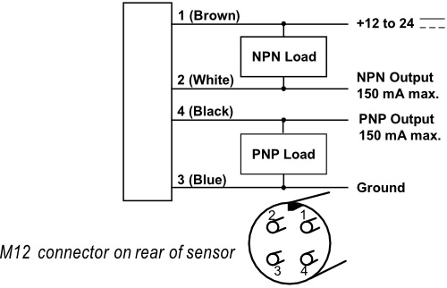
LRD8200 Wiring
| Wire Color | Connection | Notes |
| 1 (Brown) | Vin (12-24V) | 5mA max. |
| 2 (White) | NPN Output | 150mA max. |
| 3 (Blue) | Ground | Connected to sensor body |
| 4 (Black) | PNP Output | 150mA max. |
| Shield | Ground | Sensor Case |
| Any other wires in the cable (if using 5 wire) are not connected in the sensor and can be ignored. | ||
Specifications
| Power Supply | Voltage | 12-24 V (reverse polarity protected) |
| Current | 50mA | |
| Response Time | on or off | 125-425 μs max |
| Switching Frequency | 1 kHz max, 250 m/min for 2mm gaps | |
| Output | Output Current (sinking or sourcing) | 150mA max (overload protected) |
| Switching Output | PNP (sourcing) or NPN (sinking), Dark or light switching |
|
| Registration Accuracy | 60 m/min: 0.15 mm (0.006″) 250 m/min: 0.60 mm (0.024″) |
|
| Temperature | Operating Range | 40°F to 140°F (4°C to 60°C) |
| Protections | Supply | Inverse Polarity Protection |
| Switching Output | Short Circuit and Overload Protection |
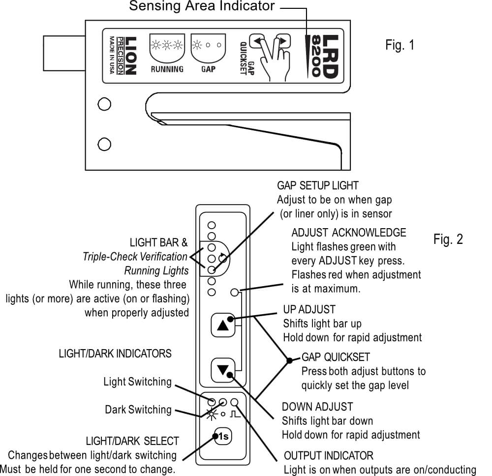
Sensor Setup
- Labels must pass under the “Sensing Area” indicator (see fig. 1).
- Place a gap in the sensor (or remove a label and place the liner only in the sensor)
- Press both Adjust buttons at the same time to quickly set the sensor, or…
- Manually use Adjust buttons to light the “Gap Setup” light on the light bar (see fig. 1, 2).
- Run labels through the sensor to verify that the three “Running” lights (see fig. 1, 2) are active (on or flashing) while labels are passing through the sensor. If not, use Adjust buttons until they are. More lights than the three “Running” lights may be active while running labels.
- If sensor is not performing satisfactorily, adjust up and/or down a few clicks and see if performance improves, but always keep the three Triple-Check lights on when running.
For best performance, web must remain in contact with the base plate.
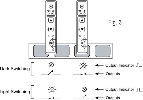
Light/Dark Switching
Light/Dark switching mode (see Fig. 3) is displayed by the Light/Dark Indicators (see fig. 2).
To change between light and dark switching, hold the Light/Dark Select (“1S”) button for 1 second.
Output
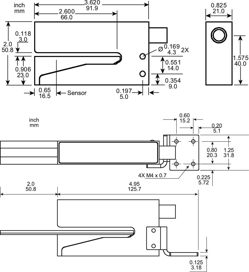
Mechanical Detail