USER’S GUIDE for the
LRD7200 Tear-Tape – Capacitive Label Sensor
Description
The LRD7200 is a combination sensor for simultaneous sensing of splices and tear strips. The sensing surfaces are contained in a separate probe body connected to the sensor control electronics by a 24″ cable.
The two separate functions of the sensor have completely independent outputs and setup. The adjustments and indicator on the top half of the sensor relate to the Splice Detector. The adjustments and indicator on the bottom half of the sensor relate to the Tear Strip Detector.
Note
The sensor head and the electronics module are calibrated together and have the same serial number. To maintain optimum performance, these components should be used together. Matched pairs should remain together.
LRD7200 Wiring
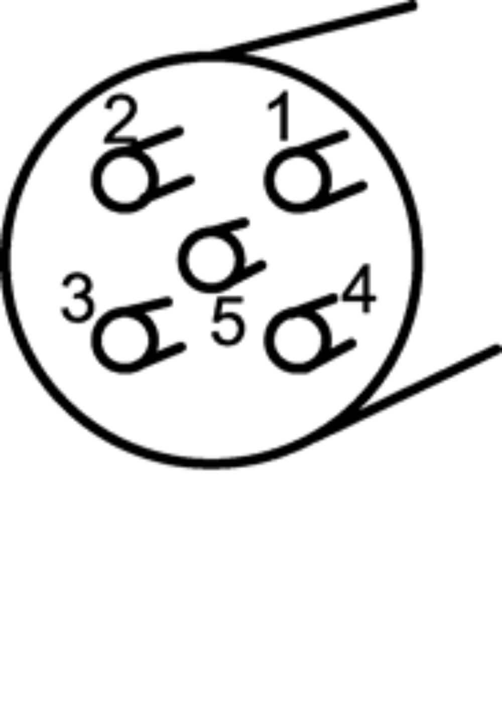
| Wire Color | Pin | Signal | Notes |
| Brown | 1 | +Vin (24 V) | |
| Blue | 3 | Ground | |
| Black | 4 | Splice Output | 0 or +V |
| White | 2 | Tear Strip Output | 0 or +V |
Specifications
| Power In | 20-26V – 200mA |
| Optimal Sensor Gap | 0.025″, 0.06mm |
| Splice Detection Response Time | 30μs |
| Tear Strip Response Time | 40μs |
| Operating Temperature | 40°F-120°F 4°C-50°C |
| Outputs | 0 or +V |
| Inter-Sensor Cable Length | 2 ft (0.6M) |
| System Cable Length | 6 ft (2M) |
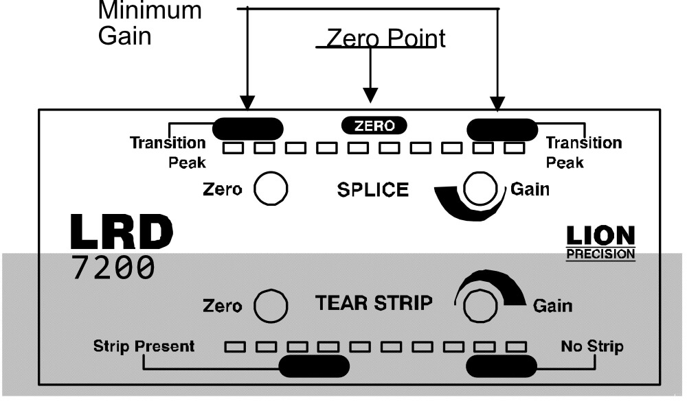
Setting up the Splice Sensor
- Remove all material from sensor, or have backing only in the sensor.
- Adjust ZERO until the indicator is at the point where it switches between the two center LEDs.
- Insert a splice into sensor assuring the splice is under the [SENSOR] area of the sensor head. When material is moved through the sensor, the indicator will move toward the ends during transitions between splice and backing.
- Adjust GAIN while moving the splice through the sensor so the indicator moves between the TRANSITION PEAKS during the transitions.
- If the indicator is going all the way to both ends during transitions, GAIN should be reduced.
- Sensor is now ready.
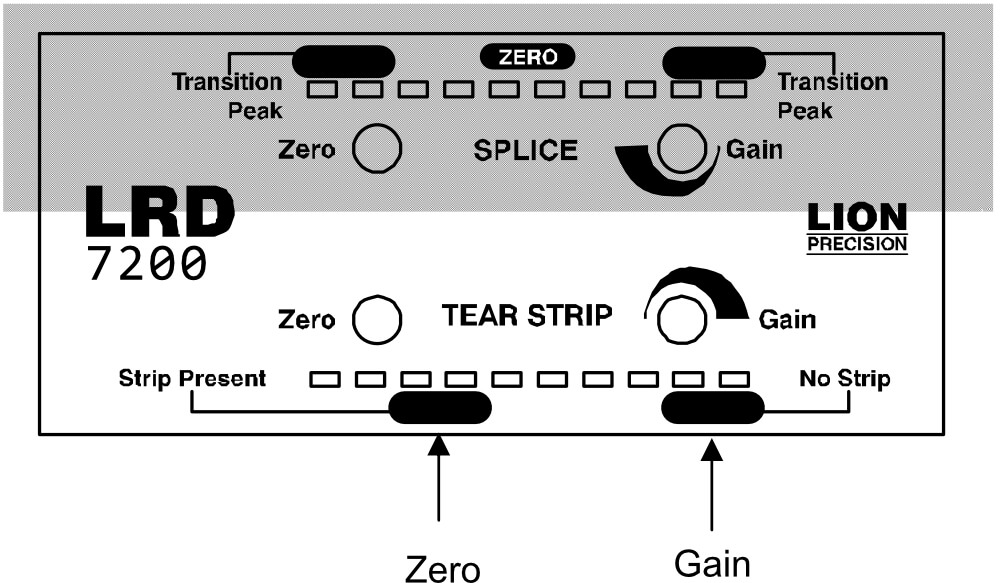
Setting up the Tear Strip Sensor
- Place material with the tear strip in the sensor. Be sure to align the tear strip with [ ] mark on the sensor head.
- Adjust ZERO to light one of the indicators in the STRIP PRESENT area.
- Place material without strip in the sensor.
- Adjust GAIN to light one of the indicators in the NO STRIParea.
- Reinsert strip material and verify the indicator is still in the STRIP PRESENT area. If necessary, repeat steps 2-4. (Large GAIN adjustments may require ZERO re-adjustment).
Warnings
- Sensor body is connected to Ground.
- Sensors must not be attached to voltages in excess of 30VRMS or 60VDC
- All external connections must be SELV (Safety Extra Low Voltage).
- All power must be off when installing the sensor.
- Use of the equipment in any other manner may impair the safety and EMI protections of the equipment.
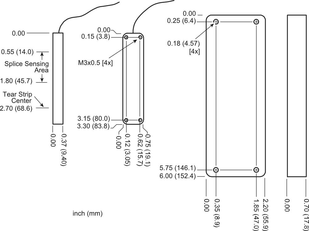
Mechanical Detail