USER MANUAL for the
LRD6110 & LRD6100C
Connecting to the Sensor
Warnings:
- Sensor body is connected to Ground.
- Unused wires must be insulated from contact with other objects.
- All power must be off when installing the sensor.
- Brown wire (Output Polarity) must be connected to +V or Ground for reliable operation.
- “Shift” adjustment will be damaged if over turned. Do not exert extra force when adjustment stops.
LRD6110 with Integral Cable
|
Wire Color |
Connection |
Notes |
|
Red |
+Vin (11-28VDC) |
50mA max. |
|
Black |
Ground |
Connected to sensor body |
|
Green |
NPN Output |
150mA max. |
|
Blue |
PNP Output |
150mA max. |
|
Brown |
Output Polarity |
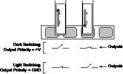
+V – Dark Switching (NC) Ground – Light Switching (NO) |
|
Warning: Brown wire must be connected to +V or Ground for reliable operation. |
||

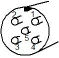
LRD6110C with M12 Connector
|
Wire Color |
Connection |
Notes |
|
1 (Brown) |
+Vin (11-28VDC) |
50mA max. |
|
2 (White) |
NPN Output |
150mA max. |
|
3 (Blue) |
Ground |
Connected to sensor body |
|
4 (Black) |
PNP Output |
150mA max. |
|
5 (Gray) |
Output Polarity |
+V – Dark Switching (NC) Ground – Light Switching (NO) |

Warning: Gray wire (pin 5) must be connected to +V or Ground for reliable operation.
Setup Procedure
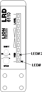
- Web must remain in contact with the mounting plate.
- Label must pass under the [-SENSOR-] indicator.
- Small labels should be centered under the [-SENSOR-] indicator.
- When properly setup, the lights will move between web and label. The lights in the “X” region should only light briefly during the transition between web and label
 Sensor Setup
- Turn Span at least four turns counter-clockwise, then two turns clockwise (this is the mid-point of the adjustment range)
The adjustment can be over turned without damage. - Place web (liner) only in sensor
- Adjust Shift until LED #2 is on, then adjust Shift just to the point where LED #1 is on.
WARNING: The Shift adjustment will break if turned too far. Do NOT exert extra force when adjustment stops turning. - Slowly move a label gap through the sensor and verify that the indicator lights LED#1 as the gap passes through the sensor. If it does not, adjust Shift as necessary until it does.
- Setup complete
If the setup does not give reliable results (usually for labels less than 1″), turn Span four turns clockwise (maximum gain) and repeat steps 2-5. It is important that the indicator only cross the “X” region during transition from web to label.
See the LRD6110 setup video at www.labelsensors.com
Notes:
- The LRD6110 may not work reliably with solid foil labels. For solid foil labels, use the LRD8200
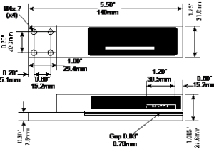
Output and Mechanical Detail
Specifications
|
Power supply |
Voltage |
11-28 VDC (reverse polarity protected) |
|
Current |
50mA |
|
|
Response time |
On or Off |
20µs max |
|
Switching Frequency |
10kHz max |
|
|
Output |
Output Current (sinking or sourcing) |
150mA max (overload protected) |
|
Switching output |
PNP or NPN, dark or light switching |
|
|
Temperature |
Operating Range |
40°F to 140°F (4°C to 60°C) |
|
Protections |
Supply |
Inverse Polarity Protection |
|
Switching output |
Short Circuit and Overload Protection |