USER’S GUIDE for the
LRD5100 Tear-Tape – Capacitive Label Sensor
Description
The LION PRECISION LRD5100 TEAR-TAPE SENSOR is an electronic, capacitive sensor used to monitor the presence of tear-tape on a film base. The sensor’s NPN and PNP outputs indicate the presence or absence of the tear-tape.
The sensor works with all types of tear-tape materials on nonmetallic film backing.
Connecting to the Sensor
Warnings
- Sensor body is connected to Ground.
- Sensors must not be attached to voltages in excess of 30VRMS or 60VDC
- All external connections must be SELV (Safety Extra Low Voltage).
- All power must be off when installing the sensor.
- Use of the equipment in any other manner may impair the safety and EMI protections of the equipment.
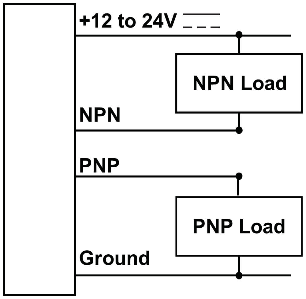
LRD5100 Wiring
| LRD5100C Wire Color | LRD5100 Wire Color | Connection | Notes |
| 1 (Brown) | Red | +Vin (12-24V) | 50mA max. |
| 2 (White) | Black | Ground | Connected to sensor body |
| 3 (Blue) | Green | NPN Output |
150mA max. 90V max. |
| 4 (Black) | Blue | PNP Output | 150mA max. Source from +Vin |
| 5 (Gray) | Brown | No Connection |
Specifications
| Power Supply | Voltage | 11-28 VDC (reverse polarity protected) |
| Current | 50mA | |
| Response Time | on or off | 20μs max |
| Switching Frequency | 10kHz max | |
| Output | Output Current (sinking or sourcing) | 150mA max (overload protected) |
| Switching Output | PNP or NPN | |
| Temperature | Operating Range | 40°F to 140°F (4°C to 60°C) |
| Protections | Supply | Inverse Polarity Protection |
| Switching Output | Short Circuit and Overload Protection |
Setup Procedure
The two adjustments are four turn adjustments. Once at the end of adjustment they will continue to turn but have no effect. Older versions of the sensor labeled the “Output” light as “Edge.”
Setup for Nonmetallic Tear-Tape
- Center the GAIN control by turning it counter-clockwise four turns, then two turns clockwise.
- With web material placed in the gap of the sensor and the tear-tape properly lined up on the “STRIP” marker, adjust the ZERO control until the ZERO light just turns on.
- Remove a section of tear-tape.
- Pass the “tear-tape missing” and “tear-tape present” sections back and forth under the sensor. If the OUTPUT light (EDGE on some models) flashes at the transitions between missing and present tear-tape, setup is complete.
- If the OUTPUT light does not flash at the transitions, turn the GAIN control clockwise until it does.
- Turn the GAIN control another ½ turn clockwise.
Setup for Metallic Tear-Tape
- Center the GAIN control by turning it counter-clockwise four turns, then two turns clockwise.
- With no material, or web material only (no tear-tape) placed in the gap, adjust ZERO until the OUTPUT light just turns off.
- Turn ZERO ½ turn clockwise.
- Verify proper operation with tear-tape present.
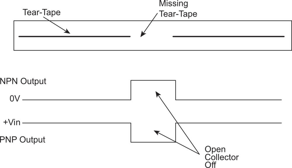
Output Waveforms
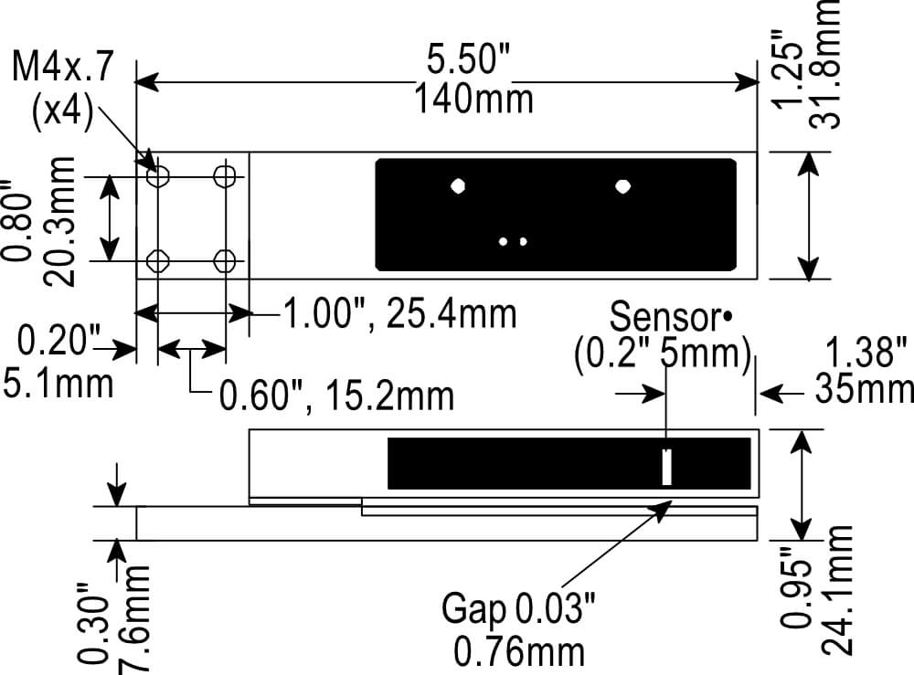
Mechanical Detail