USER’S GUIDE for the
LRD3100 – Capacitive Label Sensor
Description
The LION PRECISION LRD3100 is an electronic, capacitive sensor used to monitor label registration and/or count labels. The outputs indicate the edges of labels as they pass through the sensor.
Connecting to the Sensor
Warnings
- Sensor body is connected to Ground.
- Sensors must not be attached to voltages in excess of 30VRMS or 60VDC.
- All external connections must be SELV (Safety Extra Low Voltage).
- All power must be off when installing the sensor.
- Brown wire must be connected to +V or Ground for reliable operation
- Use of the equipment in any other manner may impair the safety and EMI protections of the equipment.
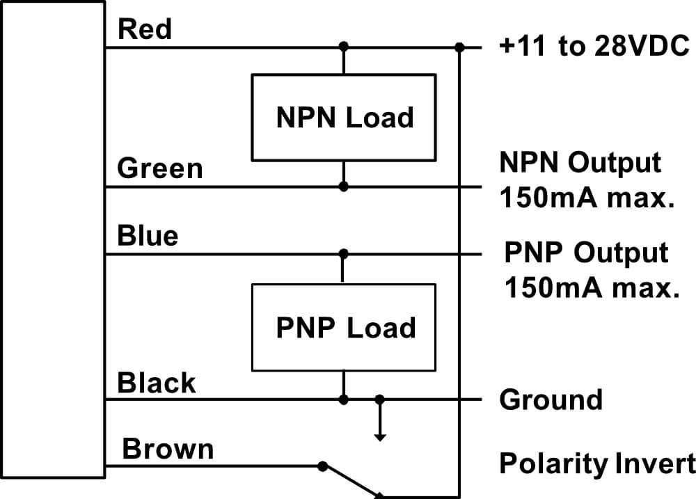
LRD3100 Wiring
| Wire Color | Connection | Notes |
| Red | Vin (11-28V) | 50mA max. |
| Black | Ground | Connected to sensor body |
| Green | NPN Output | 150mA max. |
| Blue | PNP Output | 150mA max. |
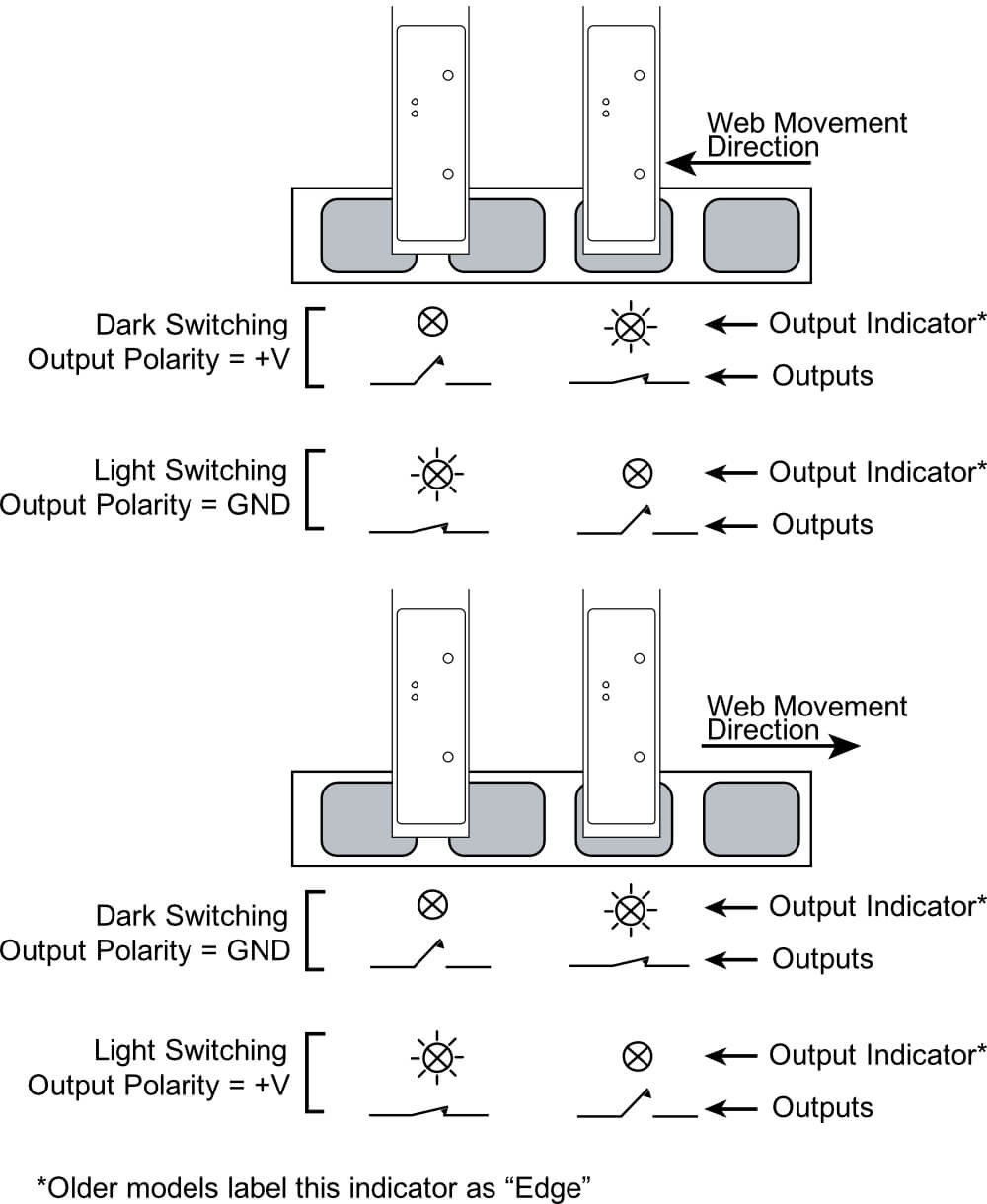
| Brown | Output Polarity (light/dark switching) | +V or Ground See detail on back |
| Warning: Brown wire must be connected to +V or Ground for reliable operation. | ||
Specifications
| Power Supply | Voltage | 11-28 V (reverse polarity protected) |
| Current | 50mA | |
| Response Time | on or off | 20μs max |
| Switching Frequency | 10kHz max | |
| Output | Output Current (sinking or sourcing) | 150mA max (overload protected) |
| Switching Output | PNP (sourcing) or NPN (sinking), Dark or light switching | |
| Temperature | Operating Range | 40°F to 140°F (4°C to 60°C) |
| Protections | Supply | Inverse Polarity Protection |
| Switching Output | Short Circuit and Overload Protection |
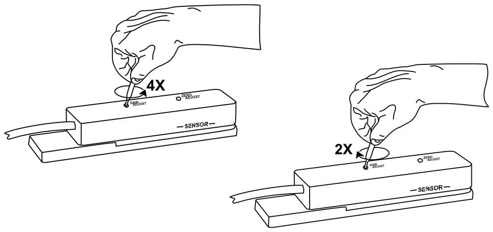
Setup Procedure
These sensors are extremely stable and should not require re-adjustment after the initial setup. Re-adjustment will on be required for significant changes in label shape or thickness, or changes in power supply voltage.
|
|
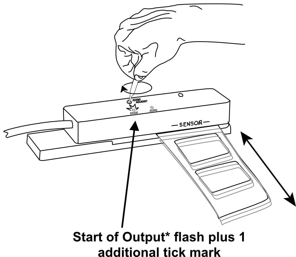
Lights During Operation
The OUT light indicates the sensor output. It will be in one state (on or off) during the label and the other state during the gap depending on the direction of the label movement and the connection of the Polarity Invert Wire (see next page for details). The ZERO light is for setup only and is meaningless during operation.
Notes
- For best results, web should ride against sensor baseplate, not “float” in the gap.
- Some inks, usually black, have high carbon content. These inks behave like metal and may not work reliably with the LRD3100. Use the LRD6300 instead.
Output
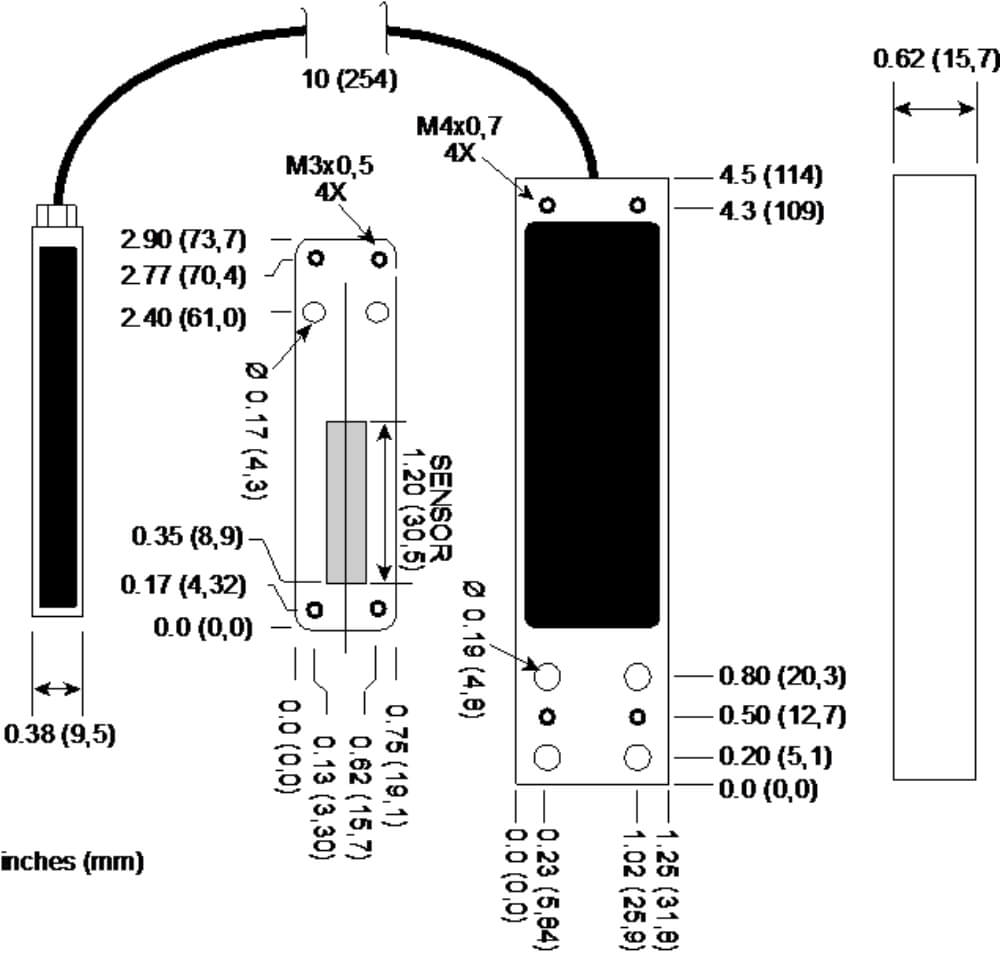
Mechanical Detail