USER’S GUIDE for the
ECL150 / ECL150e – Eddy-Current Displacement Sensor
Approvals and Safety Considerations
The ECL150 and ECL150e are compliant with the following CE directives:
- 2006/95/EC (Low Voltage Directive)
- 2004/108/EC (EMC) as validated using the following standards:
- Safety: 61010-1:2001
- EMC: 61326-1, 61326-2-3 To maintain compliance with these standards, the following operating conditions must be maintained:
- All I/O connecting cables must be less than three meters in length
- AC power cables must be rated at a minimum of 250 V and 5 A
- AC power must be connected to a grounded mains outlet rated less than 20 A
- Power supply must have CE certification and provide safety isolation from the mains according to IEC60950 or 61010.
- Sensors must not be attached to parts operating at hazardous voltages in excess of 30 VRMS or 60 VDC
- All external connections must be SELV (Safety Extra Low Voltage).
Use of the equipment in any other manner may impair the safety and EMI protections of the equipment.
ECL150 and ECL150e
The ECL150e is identical to the ECL150 except that resolution is limited to a best case of 0.3 µm. For this reason, the ECL150e does not require an export license. For details on export restrictions, please refer to www.lionprecision.com/exports-and-the-ear99-classification/
This manual will only refer to the ECL150, but all instructions apply to the ECL150e.
Description
The Lion Precision ECL150 Eddy-Current Displacement Sensor provides up to eight channels of high-resolution, noncontact displacement measurement of a conductive target. The system consists of driver electronics and probes calibrated for a specific material, range, and ECL150 channel. The ECL150 provides linear ±5 V outputs for each channel; more positive output voltage indicates the probe is further from the target. The calibration information is detailed on a calibration certificate which is shipped with the system.
Quick Start Instructions
- Connect the probes to the matching channels on the ECL150.
- Each channel is calibrated to a specific probe identified by a channel number marker on the probe cable. The probe serial numbers are listed on the labels on the end of the electronics enclosure.
- Connect the output to a monitoring device.
- Connect then apply power.
- Adjust the probe position so the Range Indicator shows green
LED Range Indicator
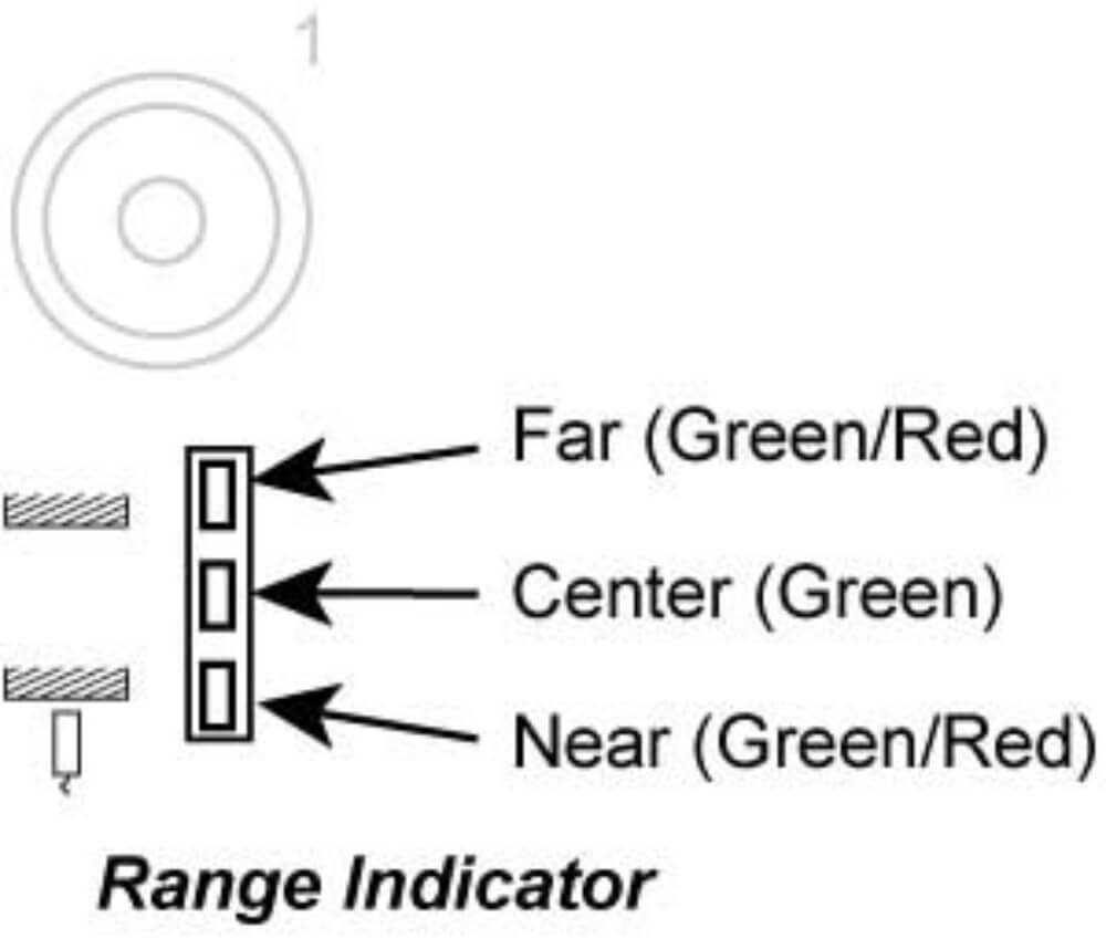 The Range Indicator monitors and displays the probe position within its calibrated range. The indicator is green when the probe is in the calibrated range and red when out of the calibrated range. If the Range Indicator is red, the output voltage is not a reliable measurement.
Analog Output Signals
Each channel’s output signal is a ±5 VDC analog voltage. The output voltage is proportional to the probe-target gap. As the probe-target gap increases, the voltage becomes more positive. See the included calibration certificate for specific information.
Interpreting the Output Voltage
Output voltage change for a given change in the probe-target gap is called sensitivity. The sensitivity of the sensor is listed on the calibration certificate.
Change in gap calculation:
Gap Change = Voltage Change / Sensitivity
For example: With a sensitivity of 1V/2 µm and a voltage change of +3 V, the probe-target gap has increased by 6 µm.
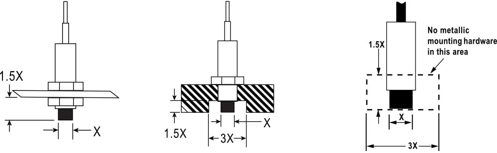
Probe Mounting
When multiple probes are mounted together, they must be separated by at least 3 probe diameters to prevent interference between the channels. The area within 3 probe diameters to the sides and 1.5 diameters behind should be kept clear of any metallic objects other than the object to be measured. Otherwise, custom calibration will be required.
Extension Cables
Sensors which are calibrated with a probe extension cable must be operated with the extension cable installed to meet specifications. Operating without the extension cable will result in inaccurate measurements.
Underground Targets
Ungrounded targets have the potential to inject noise into the sensor. If the output is unusually noisy, be sure the target is grounded. On moving/rotating targets this can be accomplished with a small metal brush or thin piece of metal which is connected to ground.
Multiple Systems
All channels within the ECL150 are synchronized and can be used on the same target. When multiple ECL150s are used with the same target, the systems must be synchronized for best performance. An interconnecting cable connects between the Sync In and Sync Out connectors. Single systems do not come with these connectors installed.
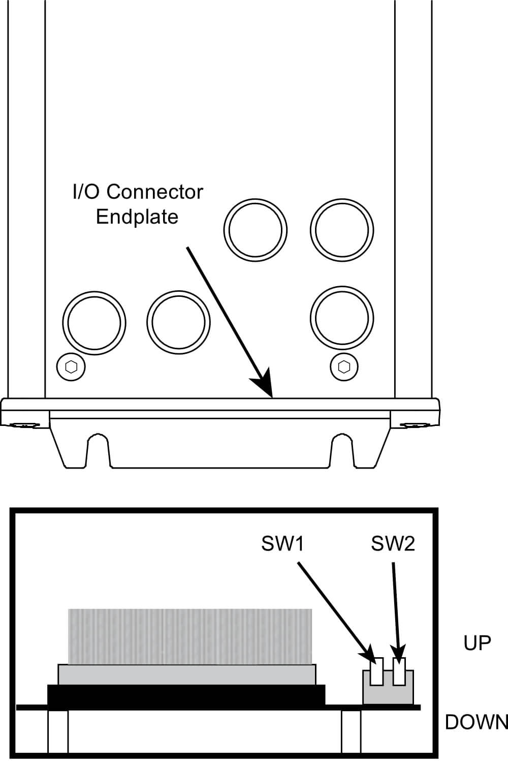
Setting Bandwidth
The system is shipped with the bandwidth setting listed on the calibration certificate based on order specifications. To change bandwidth, remove the I/O connector endplate and set switches according to the table below. Bandwidth specifications are -10%/+30%.
| SW1 | SW2 | Bandwidth |
| Up | Up | 250 Hz |
| Down | Up | 1 kHz |
| Up | Down | 10 kHz |
| Down | Down | 15 kHz |
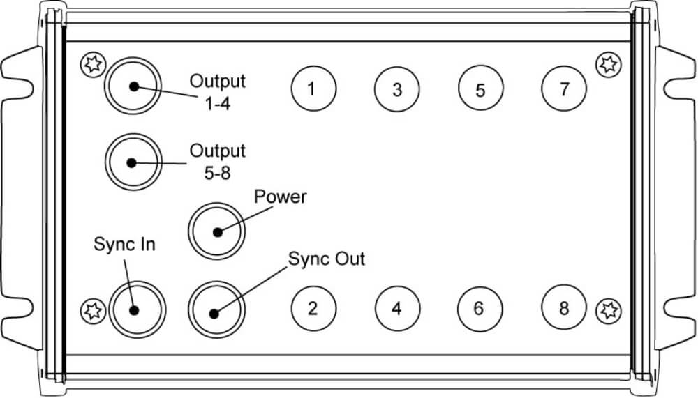
Connecting to the ECL150
The ECL150 is shipped with all required connecting cables. Power and Output connecting cables are terminated with an M12 device connector at one end and color-coded wires at the other end.
| Device Connector: 4-Pin, M12, Male Power Cable PN: 6203-0400 | 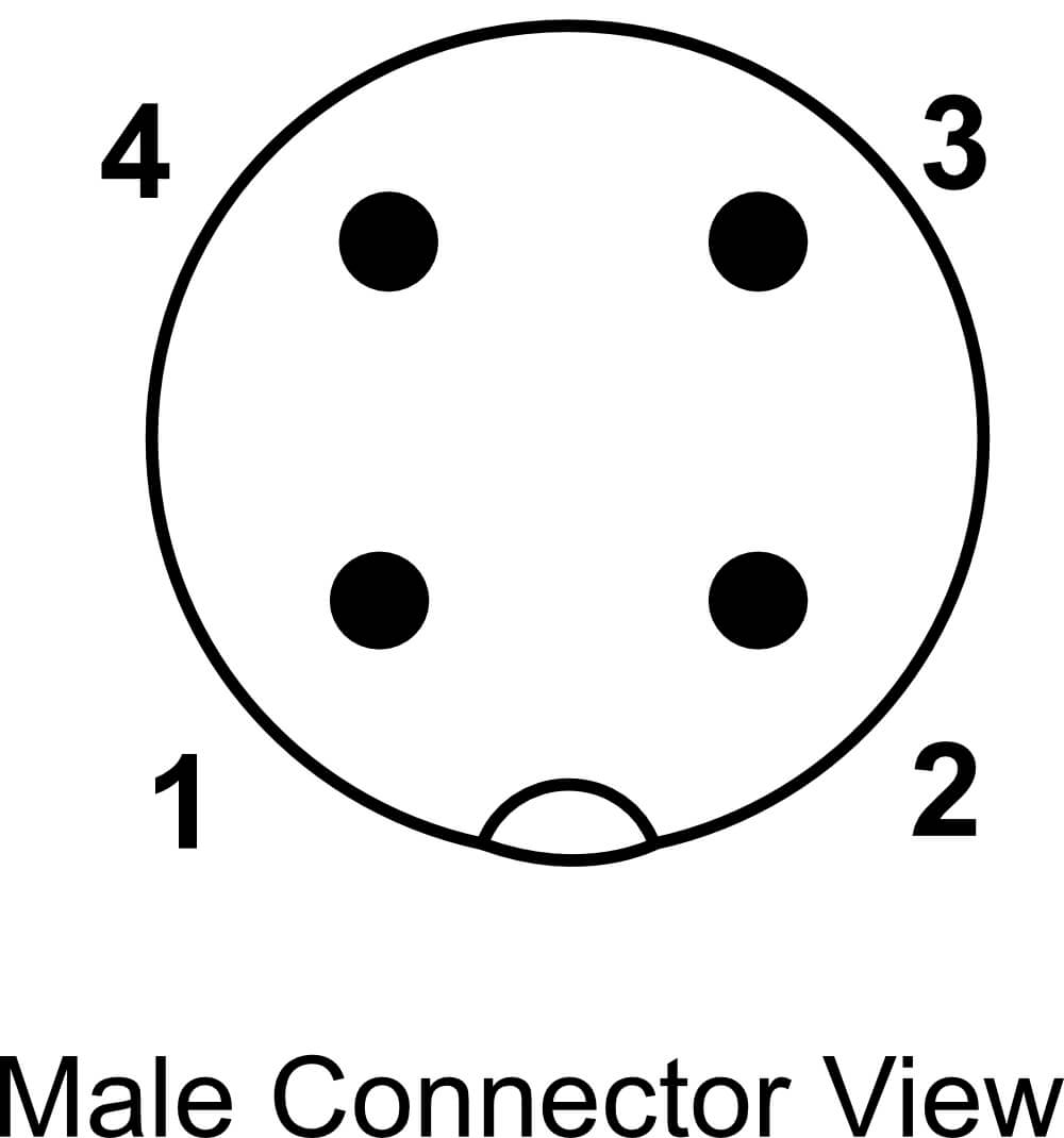 |
|||
| Pin | Wire Color | Connection | ||
| 1 | Brown | 12 to 24 VDC | Internally Connected | |
| 2 | White | 12 to 24 VDC | ||
| 3 | Blue | Power Ground | Internally Connected | |
| 4 | Black | Power Ground | ||
Sync Connections
Sync connectors are only installed when multiple systems are sold together. Connect a sync cable (Lion Precision Part Number 6203-0820) from the SYNC OUT of one system to the SYNC IN of the other system. Using multiple systems with the same target without synchronization will result in decreased performance.
Output 1-4 Connections
| Device Connector: 8-Pin, M12, Female Output Cable PN: 6203-0810 | 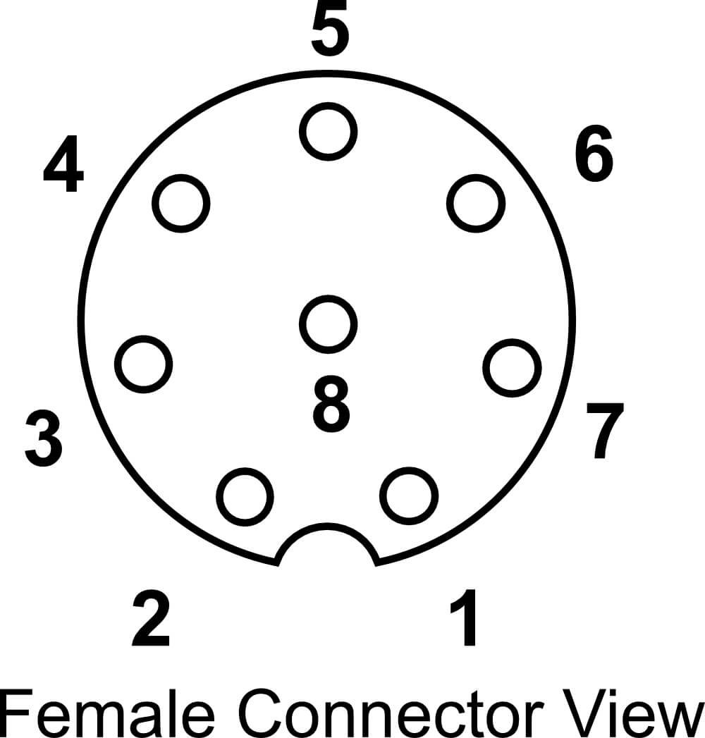 |
||
| Pin | Wire Color | Connection | |
| 1 | White | Ch1 Out | |
| 2 | Brown | Ground | |
| 3 | Green | Ch2 Out | |
| 4 | Yellow | Ground | |
| 5 | Gray | Ch3 Out | |
| 6 | Pink | Ground | |
| 7 | Blue | Ch4 Out | |
| 8 | Red | Ground | |
Output 5-8 Connections
| Device Connector: 8-Pin, M12, Female Output Cable PN: 6203-0810 | |
||
| Pin | Wire Color | Connection | |
| 1 | White | Ch5 Out | |
| 2 | Brown | Ground | |
| 3 | Green | Ch6 Out | |
| 4 | Yellow | Ground | |
| 5 | Gray | Ch7 Out | |
| 6 | Pink | Ground | |
| 7 | Blue | Ch8 Out | |
| 8 | Red | Ground | |
Specifications
| Parameter | Specification | Notes | |
| Power Requirement |
12 to 24 VDC,
1-2 Channels – 2.5 W
3-4 Channels – 3.5 W
5-6 Channels – 4.5 W
7-8 Channels – 5.5 W
|
||
| Resolution RMS @15 kHz (Typical)1, 2 | nonferrous |
ECL150: 0.006 to 0.008%F.S.
ECL150e: 0.3 µm or higher3
|
See calibration sheet for specifics |
| ferrous |
ECL150: 0.007 to 0.1%F.S.
ECL150e: 0.3 µm or higher3
|
||
| Linearity1 | ±0.2%F.S. | ||
| Error Band1 | ±0.4%F.S. | ||
| Analog Output1 | ±5 VDC, 0 Ω, 15 mA max | ||
| Analog Output Update Rate | 15 µS | ||
| Driver Operating Environment | 4°C-50°C, IP64 | ||
| Probe Operating Environment | Standard Probes | -25°C to +125°C, IP67 | |
| High Temp. Probes | -25°C to +200°C, IP63 | ||
1Actual values depend on probe and range and are listed on the calibration certificate shipped with the product. Contact Lion Precision for replacement certificates.
2In High EMI environments (10 V/m), output noise levels may rise to 60 mV (0.6% resolution) and DC level may shift by 0.2 VDC.
3The ECL150e is identical to the ECL150 except that resolution is limited to a best case of 0.3 µm. For this reason, the ECL150e does not require an export license. For details on export restrictions, please refer to www.lionprecision.com/exports-and-the-ear99-classification/
| Parameter | Specification | Notes | ||
|
Temperature Coefficient (Driver) ±% F.S./°C |
nonferrous | U3 Probe | 0.04 | Over 15°C to 50°C temperature range |
| U5 Probe | 0.10 | |||
| U8 Probe | 0.04 | |||
| U12 Probe | 0.01 | |||
| U18 Probe | ||||
| U25 Probe | ||||
| U38 Probe | ||||
| U50 Probe | ||||
| ferrous | U3 Probe | 0.08 | ||
| U5 Probe | 0.10 | |||
| U8 Probe | 0.04 | |||
| U12 Probe | 0.01 | |||
| U18 Probe | ||||
| U25 Probe | ||||
| U38 Probe | ||||
| U50 Probe | ||||
|
Temperature Coefficient (Probe) ±% F.S./°C |
nonferrous | U3 Probe | 0.04 | Over 15°C to 65°C temperature range except where noted. |
| U5 Probe | 0.04 | |||
| U8 Probe | 0.02 | |||
| U12 Probe | 0.02 | |||
| U18 Probe | 0.01 | |||
| U25 Probe | ||||
| U38 Probe | ||||
| U50 Probe | ||||
| ferrous | U3 Probe | 0.08 | ||
| U5 Probe | 0.10 | |||
| U8 Probe | 0.04 | |||
| U12 Probe | 0.03 | |||
| U18 Probe | 0.01 | |||
| U25 Probe | ||||
| U38 Probe | ||||
| U50 Probe | ||||
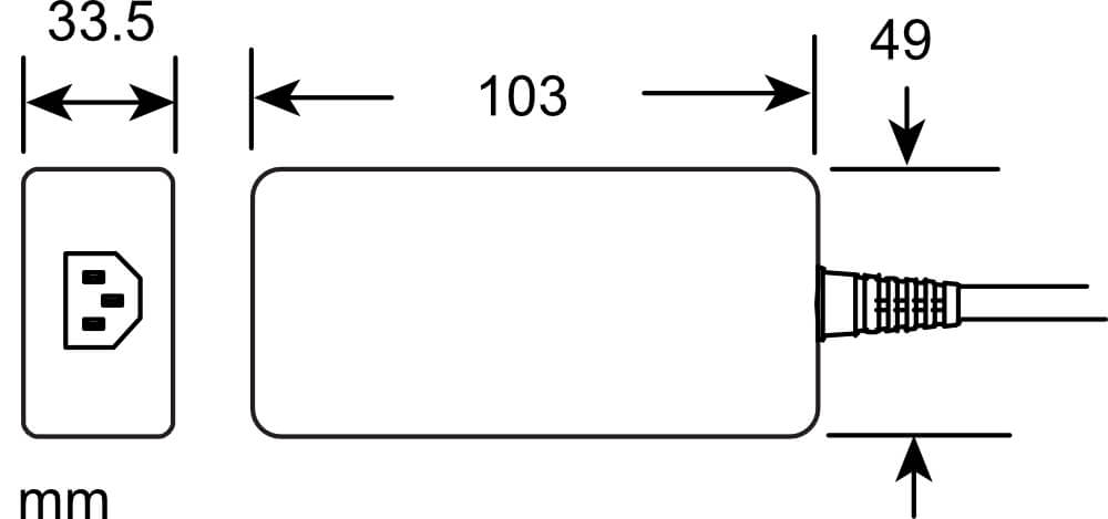
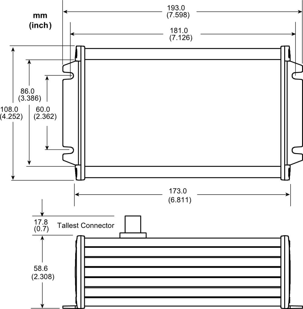
Mechanical Detail
Power Supply
Power In: 100-240 VAC 50-60 Hz
Power Out: 12 VDC @ 1.5 A (18 W)
CE and UL registered