
USER’S GUIDE for the
ECL101 – Eddy-Current Displacement Sensor
Description
The ECL101 displacement sensor consists of a probe with integral coaxial cable and a driver which operates on 12-24V DC and produces a 0-10 VDC output which are linearly proportional to the distance between the probe and the target being sensed.
Approvals and Safety Considerations
The ECL101 is compliant with the following CE directives:
Safety: 61010-1:2001
EMC: 61326-1, 61326-2-3
To maintain compliance with these standards, the following operating conditions must be maintained:
- All I/O connecting cables must be less than three meters in length
- AC power cables must be rated at a minimum of 250 V and 5 A
- AC power must be connected to a grounded mains outlet rated less than 2 0A
- Use the included CE approved power supply. If an alternative power supply is used, it must have equivalent CE certification and provide safety isolation from the mains according to IEC60950 or 61010.
- Sensors must not be attached to parts operating at hazardous voltages in excess of 30VRMS or 60VDC
- All external connections must be SELV (Safety Extra Low Voltage).Use of the equipment in any other manner may impair the safety and EMI protections of the equipment.
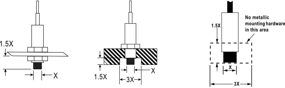
Probe Mounting
Probes must be mounted to avoid interaction with the mounting hardware and interaction between adjacent probe fields. The distance between multiple probes must be at least 3 probe diameters. The area within 3 probe diameters to the sides and 1.5 diameters behind should be kept clear of adjacent probes or any metallic objects other than the object to be measured.
If this is not possible, field calibration may be required.
 |
Extension Cables
If a probe extension cable is included, the sensor is calibrated with the extension cable attached. Operating the sensor without the extension cable may cause inaccurate results.
 Range LED Operation
Dual color LEDs indicate the relative position of the target as shown at right. One LED is illuminated whenever power is applied.
Zeroing the Output
The sensor is factory calibrated to produce an output of zero volts when the probe is at the Near Gap (nearest calibrated point) and the front panel Zero adjustment is at the center of its adjustment range. The front-panel Zero provides a ±0.5V DC shift to the output.
Remote Zero
The output voltage can also be shifted by applying ±10 V to the Remote Zero input. Positive voltage input shifts the output in a positive direction.
Note: Noise/ripple on the Remote Zero voltage will appear in the analog output.
Synchronized Systems
Sensor measuring the same target should be synchronized unless the sensors are too far apart to make it practical. Short coax interconnecting cables are provided with synchronized drivers. The cables interconnect the Sync connectors on the faces of the drivers. Do not use a T-connector on the Master Driver, identified with an “M” label. Slaves are identified with an “S” (formerly Primary “P” and Secondary “S”).
Field Calibration
Adjustments accessed from the bottom of the enclosure allow for field calibration. Any change in these adjustments will void the NIST traceable calibration certificate shipped with the sensor.
These instructions are for recalibration to the original range as shipped from the factory. Calibration to a significantly different range and/or offset will adversely affect the range LEDs operation, and temperature and resolution specifications.
A suitably precise method to accurately adjust the probe/target gap is required for calibration.
- Position the front panel Zero adjustment to the mid point (25 turns in one direction, and 12 turns back will center the adjustment).
- Set the probe/target gap to the minimum (offset).
- Use the calibration Zero adjustment on the bottom of the device to set the output voltage to 0.00 VDC.
- Position the probe/target gap to the mid-point of the range.
- Use the calibration Gain (bottom of enclosure) to set the output to 5.00 VDC.
- Position the probe/target gap to maximum.
- Use the calibration Coarse or Fine Linearity (enclosure bottom) to set the output voltage to 10.00 VDC.
- Repeat steps 2-7 until no further adjustments are needed (see hint below).
Hint: When adjusting linearity, adjust the output for the same but opposite amount of error voltage. For example, if the output is 9.950 VDC adjust it to 10.050 VDC. This will shorten the total number of iterations of steps 2-7. As the linearity adjustment approaches 10 VDC, use Fine Linearity for finer control.
Driver Connections
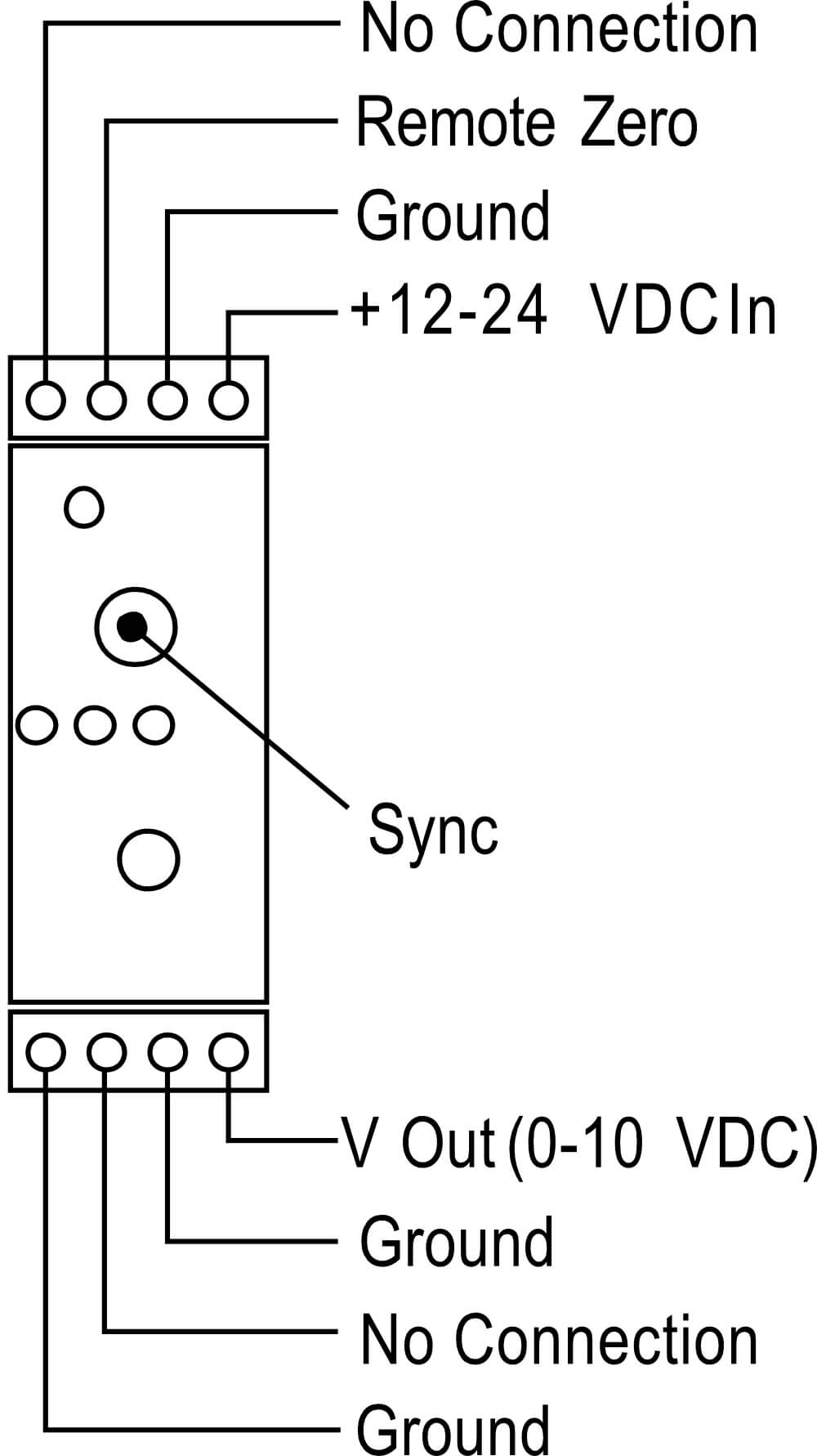 |
No Connection | |
| Remote Zero | ±10VDC input shifts output voltage. Noise or ripple on this voltage will appear in the output voltage. | |
| Ground | Internally connected to power input ground. | |
| VDC In | +12 to +24VDC @2W power input. Input voltage ripple must be less than 40mV p-p to maintain specifications. | |
| V Out | 0-10VDC calibrated output. Actual output voltage can range from –5 to +Vin when probe is out of range. | |
| V Out Ground | Internally connected to power input ground. | |
| No Connection | ||
| Ground | Internally connected to power input ground. | |
| Sync | Synchronization connection. Maximum of 1 master and 8 slaves. |
Specifications
| Analog Output |
0-10 VDC, 0 Ω,
15 mA max
|
|
| Resolution* | 0.008% typical dependent on calibration | |
| Linearity | 0.05% | |
| Probe Thermal Drift at Mid-Range | ±0.04%FS/°C | |
| Input Power | 12-24 VDC, 2 W | |
| Remote Offset (Zero) | ±10 VDC analog voltage | |
| Driver Operating Environment | 4°C to 50°C, IP40 | |
| Probe Operating Environment | Standard Probes | -25°C to 125°C, IP67 |
| High Temperature Probes | -25°C to 200°C, IP63 | |
* Specifications are based on Aluminum and/or 4140 Steel targets.
In high EMI environments (10 V/m) output level may shift and noise levels may rise to 50 mV RMS (0.5% resolution)
More Information
For more detailed information on the theory of operation and application of eddy-current displacement sensors, visit our web site at www.lionprecision.com. For applications assistance or customer service:
Call 651-484-6544,
E-mail: info@lionprecision.com