
USER’S GUIDE for the
ECA110 – Eddy-Current Embedded Displacement Sensor
Description
The ECA110 displacement sensor consists of a probe with integral 3 meter coaxial cable and a driver PCB with edgeboard connector for connecting to the users existing system PCB. It requires a DC input voltage and produces an output voltage proportional to the distance between the probe and the target. The user must provide the probe connector. Probe and PCB edgeboard connector information is specified on the adjacent page.
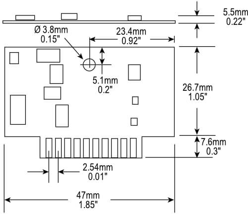
Driver
The PCB driver (signal conditioner) provides an edgeboard connector. This board has a “power on” LED and is factory calibrated to user specifications. There are no user adjustments. Model and serial numbers are on the back of the PCB. A thru-hole is provided in the PCB for rigid mounting to a motherboard via a standoff. Power in, signal out and probe connections are made through the edgeboard connector.
Probe with Integrated Cable
Probes are available in a variety of sizes and body styles according to the range and other parameters required for the application.
Calibration Record
Each sensor ships with a calibration record that provides valuable information such as:
- System serial number
- Probe serial number
- Calibration target material
- Calibration information, range, offset, output, etc.
- Date of calibration
Retain this document for future reference. If misplaced, copies are maintained at the factory.
Driver Connections
Connections to and from the ECA110 are shown below. The ten contact edgeboard connector is labeled J1 on the PCB.
| 1 | Ground | 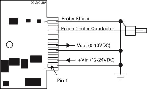 |
| 2 | +Vin (+12-24VDC) | |
| 3 | Ground | |
| 5 | V out (+0-10VDC) | |
| 8 | Probe Center Conductor | |
| 10 | Probe Shield | |
| 3, 6, 7, 9 | Not Used |
Probe Connections
For maximum performance, keep trace length from the ECA110 PCB to the probe connector to a minimum. Recommended probe connectors:
PCB Connections
Edgeboard connectors with 10oz. withdrawal force are recommended and are generally sufficient to secure the PCB. For a more rigid mounting the mounting hole can be used with a standoff and a right angle connector.
Recommended edge connectors:
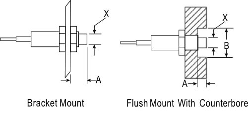
Probe Installation
Any conductive material that engages the coil field will influence the output of the sensor. If it is not possible to meet these minimum guidelines, contact Lion Precision Inductive for guidance.
| Dimensions Relative to X | |
| A | B |
| 1.5X | 3X |
Factory Calibration
The ECA110 does not provide any means for the user to modify the calibration. Output data points are provided in the calibration record. This data can be used to determine actual target position. Depending on the application, a user generated look up table or correction algorithm may be required to interpret the sensor output.
Troubleshooting
If the sensor does not appear to be performing correctly, these troubleshooting hints may help quickly resolve any operational errors. If the problem is not rectified after reviewing these hints, call Lion Precision Inductive for assistance at 800-250-9295 or 719-637-3088.
Driver LED is not lit.
There is no power supplied to the unit.
Sudden output change and/or no response to gap change.
Check that the probe is properly connected and that the cable is not damaged.
Unexpected zero shift in the output.
Probe may be damaged. Excessive target/probe contact can result in damage to the coil in the tip of the probe. Shorted turns in the coil from such contact can cause a change in output, either positive or negative based on target material. Check the probe resistance at the cable connector and compare it with other probes you may have of that same model. The resistance values should be within a few tenths of an ohm. If you do not have other probes to compare, call Lion Precision for the resistance value of that probe model.
Power is connected but nothing happens.
The ECA110 driver is protected from reverse insertion into the edge connector. Check that the PCB is inserted correctly.
The output voltage reads negative in the calibrated range.
Check the polarity of the output connections. See the Connections section of this user guide.
There is a high frequency noise on the output.
The ECA110 is designed to operate with clean input power from a linear supply regulated to ±0.5V. Check to make sure you are not using a switching power supply. Switching power supplies can inject high frequency noise into the circuitry.
More Information
For more detailed information on the theory of operation and application of eddy current displacement sensors see our web site at www.lionprecisioninductive.com.
Note the probe/driver model numbers and serial number(s) when contacting Lion Precision Inductive for assistance.
For applications assistance or customer service:
Call: 719-637-3088 or 800-250-9295
E-mail: info@lionprecision.com