USER’S GUIDE for the
ECA101 – Eddy-Current Displacement Sensor
Description
The ECA101 produces a 0-10 VDC output which is proportional to the distance between the probe and the target. The further the probe is from the target, the more positive the output voltage. The ECA101 also includes an adjustable setpoint switched output.
Approvals and Safety Considerations
The ECA101 is compliant with the following CE directives:
To maintain compliance with these standards, the following operating conditions must be maintained:
- All I/O connecting cables must be less than three meters in length
- AC power cables must be rated at a minimum of 250 V and 5 A
- AC power must be connected to a grounded mains outlet rated less than 20 A
- Use the included CE approved power supply. If an alternative power supply is used, it must have equivalent CE certification and provide safety isolation from the mains according to IEC60950 or 61010.
- Sensors must not be attached to parts operating at hazardous voltages in excess of 30VRMS or 60VDC
- All external connections must be SELV (Safety Extra Low Voltage).Use of the equipment in any other manner may impair the safety and EMI protections of the equipment.
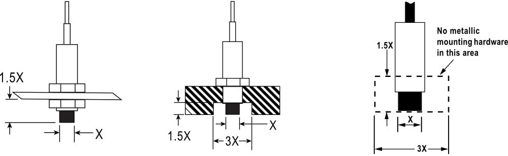
Probe Mounting
Probes must be mounted to avoid interaction between the sensing field and the mounting hardware. The area within 3 probe diameters to the sides and 1.5 diameters behind should be kept clear of any metallic objects other than the object to be measured.
If this is not possible, custom calibration may be required.
Extension Cables
If a probe extension cable is included, the sensor is calibrated with the extension cable attached. Operating the sensor without the extension cable may cause inaccurate results.
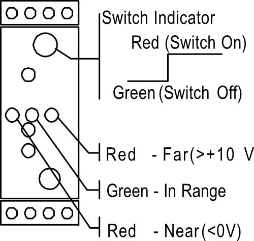 Switched LED Operation
The Switch LED indicates the status of the setpoint switch output. Red indicates a voltage above the setpoint and the switch is closed. Green indicates a voltage below the setpoint and the switch is open.
Range LED Operation
LEDs indicate the relative position of the target as shown. The center, green LED indicates that the probe is in the active range (0-10 V). Rea LEDs indicate if the probe is too near (<0 V) or too far from (>+10 V) the target.
Quick Start Instructions
- Verify that the probe serial number (heat shrink label on probe cable) matches the probe serial number on the driver side panel label.
- Install the driver on a standard EN 50 022 symmetrical DIN mounting rail in an area consistent with IP-40 requirements.
- Connect power and output according to side panel label (or this guide).
- Install the probe and route the probe cable to the driver. Fasten probe cable in place every 18″-24″. Use care not to cut or crimp the probe cable.
- Plug probe connector into the front panel driver connector. Do not twist probe connector.
- Apply power, adjust Gain and Zero if necessary to suit the application and begin making measurements. Front panel LEDs will indicate relative target-to-probe position, see driver side panel for explanation.
Calibration
The quality of the calibration is dependent on the ability to accurately set the probe/target gap to the minimum (offset), and maximum points for the calibration.
- Set the probe/target gap at the minimum distance (offset)
- Adjust Zero for 0 VDC output
- Set the probe/target gap to the maximum distance of the desired range
- Adjust Gain for desired output voltage (typically 10 VDC)
- If the output cannot be adjusted to 10V, then the system is not capable of the desired range. A smaller range must be chosen.
Adjusting the Setpoint Switch Output
- Install the probe in the application.
- Set the probe/target gap to the desired setpoint condition.
- Turn the Switch adjustment to the point where the switch LED changes from green to red.
Setpoint Switch Output
The switched output is an optically isolated, solid-state version of a mechanical relay. It operates like a mechanical switch.
Hysteresis:
To prevent switch oscillation, the setpoint voltage is changed by 0.1 V when the switch activates. For example, if the setpoint is set to 5 V, the setpoint voltage will change to 4.9V when the switch is ON. The setpoint will return to 5 V when the switch is OFF.
Driver Connections
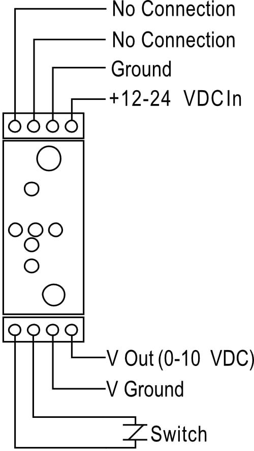 |
No Connection | No input or output connections to this terminal. |
| No Connection | No input or output connections to this terminal. | |
| Ground | Input voltage ground reference (return) | |
| VDC In | +12 to +24 VDC @ 150 mA power input. Input voltage ripple must be <40 mV p-p to maintain specifications (use linear supply). | |
| V Out | 0-10 VDC calibrated output. When the probe is out of its calibrated range, the output voltage can range from –5 to +Vin | |
| V Out Ground | Internally connected to power input ground. | |
| Switch | Switch closes when output voltage exceeds the adjustable setpoint. See Setpoint Switch Output Details on next page. |
Specifications
| Analog Output | 0-10 VDC (typical), 0 Ω | |
| Resolution* | 0.2% @ 10 kHz | |
| Bandwidth | 10 kHz (-10%/+30%) | |
| Probe Thermal Drift at Mid-Range | ±0.2%FS/°C | |
| Setpoint Switched Output | Maximum Voltage | 30 VAC/60 VDC |
| Maximum Current | 250 mA | |
| ON Resistance | 2.5 Ω | |
| Hysteresis | 0. 1V | |
| Response Time | 0.25 mS On; 0.05 mS Off | |
| Input Power | 12-24 VDC, 2 W | |
| Driver Operating Environment | 4°C to 50°C, IP40 | |
| Probe Operating Environment | Standard Probes | -25°C to 125°C, IP67 |
| High Temperature Probes | -25°C to 200°C, IP63 | |
More Information
For more detailed information on the theory of operation and application of eddy-current displacement sensors see our web site at www.lionprecision.com.
Note the probe/driver model numbers and serial number(s) when contacting Lion Precision for assistance.
For applications assistance or customer service:
Call 651-484-6544
E-mail: infolionprecision@carlisleit.com