General Sensing Application Note LA05-0021
Copyright © 2013 Lion Precision. www.lionprecision.com
Summary:
Details two methods of noncontact thickness measurement of a conductive target: Single Channel (Good), and Dual-Channel (Best). Provides cautions against common errors.
Single-Channel Method
Figure 1 – Single-channel thickness measurements assume the part is flat and perfectly seated against the reference.
Single-channel thickness measurements (Fig. 1) measure the location of the top surface of the part under test while the part rests on a reference surface. As with many noncontact applications, in-process measurements are relative to a reference measurement. A known thickness is established as a reference point and all subsequent measurements indicate the amount of deviation from that reference.
Basic Single-Channel Procedure
1. Place a part of known thickness on the reference surface .
Figure 2 – Deformed parts and reference surfaces or foreign matter between the reference and the part create a thickness measurement error in single-channel systems.
2. Adjust sensor to measure the top surface of the part. The sensor should be positioned near the center of its measurement range to allow for positive and negative deviations from the reference measurement.
3. If possible, adjust the sensor output for zero volts or a displayed reading of zero if a measurement display is being used. Otherwise, record the “master” measurement for reference when measuring test parts.
4. Replace the reference part with a part to be measured.
5. Read the deviation in thickness from the display or calculate the deviation from the output voltage.
Accuracy Limitations
The single-channel method assumes the part is perfectly flat against the reference surface. Any deformity of the part or the reference surface will result in an error in the thickness measurement. Also, any foreign matter, including air, between the part and the reference surface will also create an error (Fig. 2).
Dual-Channel Method
Figure 3 – Dual-channel systems compensate for deformities in the part or resting surface by measuring changes in position of the part’s bottom and top surface.
Dual-channel thickness measurements place the part to be measured between two sensors (Fig. 3). Each side of the part is measured by a separate sensor. The sum of the measurements from the two sensors provides the final measurement of thickness (Fig. 4). If the part moves toward one sensor, it moves away from the other; the changes in the sensors outputs will cancel each other. This eliminates the errors that would result from single-channel problems with deformity and/or contact with the reference surface.
The part can be measured with one sensor mounted in the resting surface, or the part can be otherwise suspended between the two sensors.
As with many noncontact applications, measurements are relative to a reference measurement. A known thickness is established as a reference point and all subsequent measurements indicate the amount of deviation from that reference.
Basic Dual-Channel Procedure
Figure 4 – Summing the two sensor channels produces a “thickness only” output by canceling changes of part position between the sensors.
1. Place a part of known thickness between the two sensors.
2. Adjust sensor positions to measure the top and bottom surfaces of the part. The sensors should be positioned near the center of measurement range to allow for positive and negative deviations from the reference measurement.
3. If possible, adjust the sensor outputs for zero volts and a displayed reading of zero when using a measurement display with summing capabilities (see recommendations below).
4. Replace the reference part with a part to be measured.
5. Read the thickness deviation from the display with summing capabilities or calculate the deviation by adding the two output voltages and converting to dimensional units.
Dual-Channel Example
The illustrated example uses two sensors which are calibrated for 10V/1mm. Condition 1 sets a 1mm thick target as a reference at 0 volts. Condition 2 shows the effect of moving the 1mm thick target closer to one sensor. Condition 3 shows the noncentered measurement of a test part which is 1.5mm thick.
Important Cautions
One of the biggest challenges in making high-resolution thickness measurements is the design of the probe mounting system and the way the test material is positioned in the measurement area.
Any changes in distance between the probe and target surface will register as thickness changes in a single probe system. Anychanges in distance between the two probes in a dual probe system will register as a thickness change. When making measurements at a precise, sub-micron level, movement of the probe mounting system that it is too small to be seen will skew the measurement results.
Rigid probe mounting and test material positioning is critical to precise results. Any vibration, thermal expansion/contraction, or other movement of the probes or material will prevent reliable results. Do not take this lightly; if you want to measure microns, you must control probe position stability better than microns.
Problematic Examples:
Hot Material
A common thickness measurement application is to monitor material thickness as it is conveyed during processing. This sometimes means the material is hot. In addition to all the concerns about probe and material position stability during conveyence (see below), the hot material will heat the probes. All non-contact probes have some sensitivity to temperature changes. Varying temperature of the probes will mean varying measurements of thickness.
The thermal specifications of the sensors must be considered and calculated for the application; shifts due to thermal changes must be less than the desired precision of the thickness measurement.
In more extreme cases, probes may heat beyond their environmental limits and be damaged. Environmental specifications of the probes must be considered for the application.
Thickness of Material Passing Over a Roller
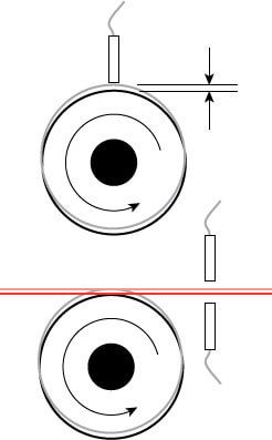
Roller runout (radial displacements while the roller turns) makes thickness measurement a challenge by introducing erors often larger than the desired thickness measurement accuracy.
Measuring thickness of a material as it passes over a roller presents difficult challenges.
The roller’s ‘runout’ (radial movement of its surface as it turns) is almost always larger than the precision required for the thickness measurement.
Single Probe Method
Using a single probe directly over the roller to monitor the material’s top surface will not work unless the roller runout is considerably less than the precision of the thickness measurment; this is rare. With more extreme runout, the roller runout may be larger than the measurement range of the probe, especially if the probe is small.
If the measurements stay in range, it is possible to compensate for roller runout. The system can measure the runout of the roller and subtract it from the thickness measurement. But the probe monitoring the runout must be near and at the same angular location as the thickness probe because the runout is not consistent at all locations on the roller.
Dual Probe Method
One approach to solving the roller runout problem is to use the dual probe method where the material is suspended immediately before or after the roller. In principle, this is a reasonable idea; however, the material is still deflected by the roller runout as well as instability or runout in other mechanisms supporting the material. The dual probe method will minimize errors as the material moves up and down in the gap between the probes, but the those movements must not.exceed the measurement range of the probes.