Summary:
Shaft runout is a common measurement especially for condition monitoring. Capacitive and eddy-current sensors provide useful non-contact measurement solutions with distinct advantages and disadvantages.
Fundamentals
Runout is the displacement of the surface of a rotating object. Non-round shafts will have significant runout by definition.
According to ASME/ANSI B5.54-2005 Methods for Performance Evaluation of Computer Numerically Controlled Machining Centers, “runout” is the total indicator reading (TIR) of an instrument measuring against a moving surface. This is usually a rotary motion and is measured for a full rotation. This means the runout value is a combination of several types of error motions, form errors, and form factors:
- shape of the shaft
- straightness of the shaft
- centering errors in the location of the shaft relative to the axis of rotation (eccentricity), and
- errors in the axis of rotation itself which itself is a product of several factors:
- drive bearing performance
- machine structure
- drive alignment (tilt)
- measuring instrument errors (indicator or sensor)
While techniques exist for refining a shaft runout measurement to just one or a few of these components, the purpose of this Application Note is to measure total runout with all of its contributing factors (except sensor errors). The techniques described here are intended to minimize or eliminate the sensor’s contribution to the final result. When properly applied, noncontact eddy-current and capacitive sensor measurements of shaft runout will produce results with negligible sensor errors.
Radial Shaft Runout
Radial runout is perpendicular to the axis of rotation.
Radial shaft runout is a measurement of radial displacement of the shaft surface as the shaft turns. Assuming a round shaft, contributing factors to radial runout include shaft straightness, drive/shaft alignment, bearing stiffness, and increasing runout as the bearings wear. Balance is a runout factor that is dependent on the relationships between speed and bearing stiffness and wear, and overall system stiffness. Radial shaft runout is generally used to indicate wear in the drive bearings.
Axial Shaft Runout
Axial runout is measured at the center of rotation to prevent shaft end flatness/squareness errors from affecting the measurement.
Axial shaft runout is a measurement of the axial displacement of the shaft as it rotates. This measurement is taken at the center of the shaft (on the rotary axis). Off-center measurements are called “face runout” in which the flatness and squareness of the surface become contributing factors to the measurement – factors which are not of interest in most applications. Axial shaft runout is primarily used for condition monitoring of the thrust bearing.
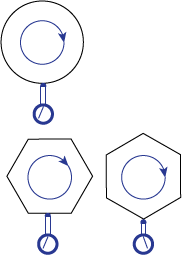
Shaft Shape
By the definition above, non-round shapes always have significant runout. An oval or hexagonal shaft which is rotating perfectly will still have significant runout as the indicator responds to radial displacements of the shaft surface due to the shaft shape.
This Application Note assumes that the shaft being measured is round.
Shaft Straightness
Shaft straightness affects the runout measurement.
Radial runout is affected by shaft straightness. If the shaft is bent, runout measurements will be dependent on the location of the measurement along the length of the shaft and the location and severity of the bend. If a shaft is fixed at both ends (e.g. between the drive and a gear box) the maximum runout will tend to be near the center. If the shaft is only fixed at the drive end (e.g. motors driving fans or propellers) the runout will tend to be worse at the floating end of the shaft.
An otherwise straight shaft may be mounted such that the center line of the shaft is not parallel with the axis of rotation. In this case, runout measurements will depend on where the measurement is taken along the shaft.
Synchronous and Asynchronous Shaft Runout Components
Some runout components such as shaft out-of-roundness or a tilt in the drive will repeat at certain angular locations of the rotation; these are synchronous error motions. Other shaft runout components such as bearing frequencies (runout due to out-of-roundness of rolling elements in the bearing) are cyclical but do not repeat at the same angular locations and are called asynchronous error motions.
Real-Time/Instantaneous
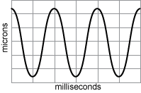
Real-time displacements of the rotating shaft can help identify specific problems but is a more complicated measurement.
Instantaneous values of radial or axial shaft displacement can be measured and recorded at each angular location as the shaft rotates. This provides a picture of the instantaneous displacements that contribute to the total runout measurement. This approach is used for balancing operations or to help identify specific causes of runout. These types of measurements require comparatively sophisticated techniques and tools such as Lion Precision’s Spindle Error Analyzer. This Application Note is focused on a single measurement of total shaft runout.
Total Shaft Runout
In many circumstances, especially condition monitoring, the only value of concern is a single value indicating total shaft runout. This number is usually an average or peak of multiple TIR readings over a period of time and multiple rotations. As bearings and other components wear, the total shaft runout will increase. In condition monitoring, a threshold value is set above which the system is shutdown and repair or rebuild is commenced.
Runout Measurements With Noncontact Sensors
Measuring shaft runout while in operation requires a non-contact sensor. The types of sensors best suited to this measurement are capacitive displacement sensors and eddy-current displacement sensors (sometimes called inductive displacement sensors).
Capacitive or Eddy Current
Capacitive displacement sensors offer high precision; they work equally well with all conductive materials; they work well with small diameter shafts. But they require a clean environment. Eddy-current displacement sensors work in wet, dirty environments and can be mounted further away from the shaft. But they must be calibrated to a specific material, don’t work as well with smaller shafts (< 8 X Probe Diameter), and are more “noisy” when used with magnetic steel shafts because of “electrical runout” (see details below in the Eddy-Current Considerations section).
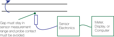
Mounting the Probe
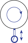
These non-contact sensors consist of a probe (measurement head) which is connected via a cable to electronics that drive the probe and provide an output voltage proportional to the changes in distance between probe and the shaft.
The probe is mounted at a distance from the shaft approximately at the center of its measurement range. This allows for maximum excursions of the shaft in both directions to stay within the probe’s functional range.
After the probe is mounted, rotate the shaft slowly to check the range. Be sure the probe will not contact the shaft at its closest point and that it stays in range throughout the entire rotation.
Any change of distance between the probe and shaft will be part of the shaft runout measurement. Therefore, it is important that the probe be rigidly mounted to prevent vibration or other external movements from displacing the probe relative to the shaft.
Deriving Total Shaft Runout
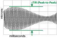
“Total Runout” can be measured with TIR (peak-to-peak) captures of the runout signal.
The shaft runout measurements from the non-contact sensor track the instantaneous displacements in real-time as the shaft rotates. This output must be conditioned to derive a single “total runout” measurement. The runout value can be a type of average value or a peak value. The specific method for creating a total runout value will depend on the application.
Typically, a baseline runout value is set as well as a threshold above which the system needs operator attention. In this type of condition monitoring system, the units of measurement are not critical; whatever the units, the establishing of baseline and threshold values is the critical piece of the measurement.
Average Values
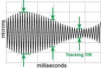
Changing “total runout” can be measured with Tracking TIR option of the MM190 Module.
The output values can be averaged over time by using some type of AC voltmeter. These are available as discrete instruments or may be available in support software for a data acquisition system. It is important to consider the meter’s ability to measure at the rotational frequency of the shaft.
Peak Values
Peaks of output values can be captured and the system can report the difference between the maximum and minimum peaks. This is a TIR (total indicator reading) measurement. Systems that capture these peaks have to be periodically reset to keep the value current should it decrease. If using Elite Series capacitive sensors for shaft runout measurement, the MM190 Meter and Signal Processing module can capture and display peak values. The MM190 also has Tracking TIR which captures peak values but allows the values to decay with time; this way, the displayed value is kept current without a reset being necessary, even when the runout is decreased. The MM190 is not an option for eddy-current sensors.
Unique Considerations for Eddy-Current (Inductive) Measurements of Shaft Runout
Eddy-current sensors are calibrated for a unique material. To maintain precision, the sensors must be used with that specific material.
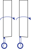
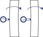
Eddy-Current sensors are normally calibrated to a flat target. Shaft diameter should be 8-10 times larger than the eddy-current probe diameter to provide a sufficiently flat target for accurate measurements. Also, because eddy-current sensors will interfere with each other if too close together, a shaft diameter of this size provides sufficient spacing between probes when two probes are used to monitor runout at 90° apart.
Electrical Runout
Eddy-current sensors read “electrical runout” errors from magnetic steel materials; capacitive sensors do not.
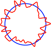
Magnetic materials have a property called electrical runout. Small localized differences in magnetic properties within the material affect the interaction with eddy-current sensor magnetic fields. The differences result from local chemical composition, crystal structure and magnetic domains which are affected by heat history, degree of cold work stress, surface treatments and exposure to magnetic fields. The greater these differences, the larger the electrical runout. As the magnetic steel shaft turns, the eddy-current sensor output will change in response to the electrical runout of the material even if the gap between the sensor and shaft does not change (no mechanical runout). Images at the right compare a capacitive sensor and eddy-current sensor measuring the same magnetic steel shaft. Non-ferrous materials like copper and aluminum do not have this phenomenon at any significant level. Non-magnetic steel, while better than magnetic steel, still exhibits a small electrical runout.
The electrical runout is usually less than 75 µm (0.003 inches) which is often only a fraction of the measurement range of the eddy-current shaft runout sensor. In some applications, the electrical runout is small in comparison with the baseline runout of the shaft and therefore does not introduce any significant error in the total shaft runout measurement.
Mitigating Electrical Runout
If your shaft runout measurement need be so precise that electrical runout will be a significant error, you will have to address the problem. The best way to eliminate electrical runout errors in magnetic shafts is to use capacitive sensors. But shaft runout sensor applications are often in a wet and dirty environments that require an eddy-current sensor. Here are some methods for eliminating or reducing electrical runout.
Use the largest probe possible. The sensing field of an eddy-current shaft runout sensor is three times larger than the diameter of the probe. The probe output is an average of everything within that field. Using a larger probe will average a larger area of the shaft and its localized magnetic inconsistencies. But be sure not to use a probe too large for the shaft (see above).
Non-magnetic sleeve. The eddy-current sensing field does not penetrate very deeply into the material. A 0.5 mm (or thicker) aluminum or copper sleeve will provide a non-magnetic target for the shaft runout sensor.
Conclusion
Measuring shaft runout is a common and useful measurement, especially for condition monitoring. Using a single sensor and a method to derive a single, total runout value enables you to set baseline runout numbers and thresholds for operator intervention. Capacitive and eddy-current sensors both provide excellent solutions depending on measurement specifics and the environmental condition of the application.
General Sensing Application Note LA05-0022
Copyright © 2013 Lion Precision. www.lionprecision.com