Introduction
One of the key components of a machine tool is the spindle; the machine could have a perfect structure and guide-ways, but if the spindle axis moves, the work-piece will present geometrical form errors [1]. Through the years several methods have been developed to characterize spindle axis motion from crude run out tests [23], to several contact and non-contact methods using LVDT’s, inductive probes and capacitance probes [5]. Today the most accepted method uses a master target and capacitance probes instrumented and connected to a personal computer where all the calculations are made.
This modern axis motion measuring instrumentation is capable of sub-micron resolution and accuracy. This equipment mostly finds its place in air bearing and hydrostatic spindle research and manufacturing, since the machines where these are used require ultraprecision components. While this may be true, modern spindle axis motion measuring is also a valuable resource for the Super Precision® machine tool manufacturers[4]. The information acquired from these measurements can help in finding spindle defects and their sources. It can also identify if certain assembly process changes have a positive or negative impact. In the following paragraphs it will be shown how the measurement of spindle axis motion provides valuable advantages to the Super Precision® spindle manufacturer.
Purpose of Measuring Spindle Axis Motion
The part roundness is determined by a test cut performed on the completed machine. At this point the spindle has been assembled on the machine, where several covers and support systems have been installed. If the spindle does not meet the required specification, it will be rejected and several hours of assembly time are wasted. This creates the need for a spindle quality performance test. For a Super Precision® turning center the roundness should be under 0.50µm (20µin). The manufacturing process to achieve this roundness has been established and for the most part is stable.
Nevertheless if a nonconforming spindle is detected before it can be installed on the machine, unnecessary waste is avoided. Measuring the roundness of the spindle requires a source of driving power, a work-holding device for the sample part and a guiding system for the tool. Supplying all these elements for a spindle which is not installed on the machine tool is impractical, cumbersome and can introduce additional errors to the roundness measurement. Taking these factors into consideration, it was determined that the most feasible characteristic to measure when the spindle is outside the machine tool is the spindle axis motion; which subsequently can be correlated to spindle roundness.
The spindles being measured are used in a super precision turning center. The spindle is driven by a multi-strand V belt transmission when installed on the machine. During the production process the spindle requires a run-in procedure to purge the grease. At this stage performing a spindle measurement is ideal since it can be easily instrumented and driven. The main objective, after the spindle axis motion has been acquired, is to find the relationship between this information and the part roundness.
Hardware and Measurement
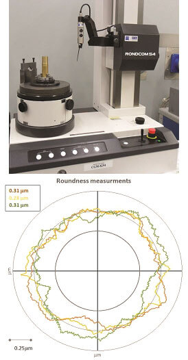
FIGURE 1. Roundness measuring machine Rondcom 54 (top). Output of roundness measurement (bottom), the three measurements are used to compute the cut average roundness.
Two key parameters that need to be measured are: part roundness, which is the output, and spindle error axis motion, which is the input. The part roundness measurement is simple and straight forward. A C360 brass 1 inch diameter specimen is cut at 1000rpm using a natural diamond at a feed rate of .0009ipr. The length of the cut is also 1 inch and 3 roundness measurements are taken: top middle and bottom. The average of these three measurements is the part roundness value used and recorded in the inspection files, see figure 1.
The spindle axis motion is measured using a 3 channel LION precision© spindle analyzer when mounted on the run-in bench. In general terms this equipment is a set of capacitance probes that measure the relative distance from a master target when the spindle is rotating. All this data is processed by the spindle analyzer software [5]. The capability and amount of information that can be obtained from this device are immense, however, we will concentrate on the radial motions of the spindle since they are related to part roundness.
The capacitive sensors are secured by a probe nest, which is mounted to a fixture that has fine adjustment screws for alignment; as shown in figure 2.
To obtain the bench natural frequency a bump test is performed. When the fixture is secured to the running bench the natural frequency of the setup is 64 Hz which is higher than the testing rpm frequency of 16Hz. This is key to avoid any resonance of the fixture structure that could potentially affect the measurements [6].
In addition, the noise of six different spindle setups in the running bench with the spindle stopped was measured. It was found that the average peak to peak value of the noise is 0.07µm. Since this value is an order of magnitude smaller than what we are looking for, the measurements can be considered reliable. The noise contains some frequencies on the 60 Hz range and its harmonics, most likely introduced by the surrounding electrical systems. In case the idle noise levels are on unacceptable range, the measurement setup is checked and the detected noise sources are eliminated.
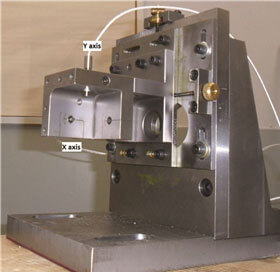
FIGURE 2 Run-in bench fixture used to hold the probe nest. Note the oversized steel plates used.
The signals from the X & Y sensors are logged at a sampling frequency of 5kHz. The data of these two channels are plotted on a rotating sensitive direction graph by the spindle analyzer software. This graph is visually inspected to detect any major anomalies or problems. Our main interest is the data collected by the X axis probe, which is the sensitive direction. For a lathe the sensitive direction is where the tool is perpendicular to the axis of rotation on the X-Y plane. Any spindle motion along this axis will have a direct effect on machined part roundness [1].
Several approaches exist to analyze the error axis motion, from simple time domain techniques to advanced frequency domain filtering [1],[6]. The synchronous (or average) error motion has been selected as the main analysis parameter, due to its stability and self filtering nature. The synchronous error is the component of the total error motion that occurs at integer multiples of the rotation frequency [5]. It is typically obtained by averaging a certain number of revolutions and calculating the distance between the minimum and maximum inscribed circles. From the physical point of view it also makes sense to use the synchronous error, because during the cutting process most of the asynchronous errors will be part of the surface finish[1] and not the form.
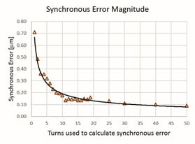
FIGURE 3. Using the same axis motion data set the synchronous error was calculated for different number of turns, an exponential behavior is readily observed.
To simplify the axis motion measurement, no encoder is used; the angle of rotation is obtained by leaving a small amount of eccentricity (10µm) on the master target. This adds a sinusoidal component to the sensor data, which is removed by fitting a least squares sine wave to the data. The fitted sine wave is also used to obtain the rotation angle of the spindle.
The number of turns used to calculate the synchronous error motion is not a trivial matter. The behavior between the synchronous error magnitude and the number of turns used is exponential, as shown in figure 3. Taking this into consideration, if not enough turns are used, the synchronous error will be too high. On the other hand if too many turns are used information from the synchronous error will be lost due to the averaging. A good balance was found when using 10 turns to calculate the synchronous error motion, since its where the exponential starts to flatten out. In addition the default value for number of turns used on calculations on the LION© spindle analyzer is also 10.
Expected Roundness Model
Our main objective is to relate the measured axis motion of the spindle at the running bench with the machine roundness cut average. The output of the machine roundness cut depends on several factors, some are directly related to the spindle itself and others depend on the machine assembly. This is important to understand because there is a source of variation which is not related with the measured spindle axis motion. To minimize the effect of this variation the roundness cuts are taken after the machine has been properly balanced and aligned. A spindle is considered unacceptable if the average roundness cut is above 0.50µm.
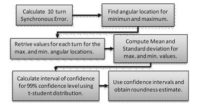
To obtain a value for the expected roundness the spindle axis synchronous error was calculated by dividing each revolution in 2 degree intervals, averaging the motion for 10 turns, and taking the difference between the maximum and minimum averages. This calculation is considered as the mean roundness; however, this value is not a full representation of the process. With this in mind, the values that define the maximum and minimum over the 10 turns are used to obtain the standard deviation. With the means and the standard deviations the Student t-distribution [7] is used to calculate the upper interval of confidence for the maximum and the lower for the minimum. The difference between these intervals is our expected roundness. Figure 4 shows the steps used to calculate the expected roundness.
A confidence level of 99% was selected since the main objective is to avoid installing a bad spindle on a machine. When this happens a great amount of time and money are wasted.
Test Results
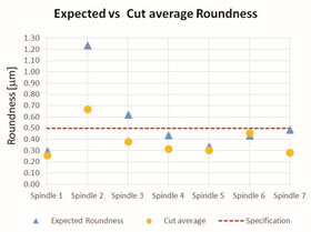
FIGURE 5. Expected roundness and actual cut part roundness obtained from the average of three measurements.
The proposed approach was applied on 7 production spindles, by measuring the axis motion on the running bench computing the expected roundness and then measuring the roundness from test cuts. These results are shown in figure 5.
It can be observed that six of the seven expected values were accurate in predicting if the spindle would pass or fail the roundness cut.
Spindle 3, where the expected roundness indicated that the spindle would not pass, shows that the method works as a failsafe. Since qualifying a bad spindle as good is much more costly than the opposite scenario. When the prediction is a higher roundness value than the maximum allowed (0.50µm), the spindle is further checked to determine if a fault exists.
Conclusions
When using the spindle error axis motion an expected roundness can be computed with a confidence level of 99%. This provides a valuable tool for manufacturing, avoiding the assembly of spindles that will not pass the roundness cut. It is understood that some inherent variability comes from the machine assembly and not only from the spindle axis motion. Examples of machine assembly factors that affect roundness include: balancing, axis vibration, machine stiffness, part material, tool material, cutting parameters, auxiliary equipment vibration, etc. Taking this into consideration another benefit of the proposed expected roundness computation is that it can help to pin point if the problem is on the machine or spindle assembly.
Acknowledgements
The authors wish to thank all the support of Terry S. George C. and Matt B. during the development of this methodology. Furthermore we like to acknowledge Hardinge Inc.
Refereneces
- B. Bryan, P. Vanherek, “Unification of Terminology concerning the error motion of axes of rotation” June 20, 1975, CIRP
- J. Goddard, A. Cowley, M. Burdekin, “A measuring system for the evaluation of spindle rotation accuracy” September 18, 1972 13th International machine tool design and research conference.
- Schlesinger, “Testing of machine Tools”,1966 7th ed, Machinery Publishing Co. Ltd.
- Kushnir, “Super-precision turning center: high accuracy, hard turning, multi-tool machine tool” October 20, 2013 ASPE
- Lion Precision, “Instruction Manual Advance Spindle Error Analyzer v7”, 2003
- R. March, “Precision Spindle Metrology” 2010, 2nd ed, DEStech Publications
- C. Montgomery, “Introduction to Statistical Quality control”, 2009 6th ed, John Wiley & Sons