Spindle Analysis TechNote LT03-0013
Copyright © 2015 Lion Precision. www.lionprecision.com
Download PDF File
Summary
Dimensional detail, care instructions, and eccentricity adjustments for master-ball targets and probe nests.
Care of the Targets
The targets used with the Lion Precision Spindle Error Analyzer are precision components which require special handling. Precautions are similar to those used when handling gage blocks.
Avoid touching the master ball surfaces (or gage pin surface) with bare hands. If the targets are touched and stored without proper care, it is possible for a fingerprint to become rusted onto the surface. In many cases, this damage cannot be repaired.
Steps for using a precision target:
- Remove the target from its protective case
- Remove the cloth cover from the target
- Wipe target with dry, clean cloth to reduce oil film thickness
- Mount the precision target onto the spindle
TAKE CARE TO AVOID TOUCHING THE TARGET SURFACE
When finished using the precision target:
- Apply a thin coating of light oil, such as gage block cleaner/lubricant to the target surface
- Place the cloth cover over the target
- Place the target back into its protective case
These simple precautions will keep your precision targets clean and free from rust.
Target Dimensions
Precision pins and master ball spheres are 440c SST hardened to 57-60 Rc; the ball mounts are 416 SST hardened to 40-43 Rc.
1″ Diameter Single Ball, Fixed Eccentricity
Maximum speed: 60,000 RPM
Maximum roundness error: 50 nm, 0.000,002″
1″ Diameter Single Ball, Adjustable Eccentricity
Maximum speed (runout < 25 µm, 0.001″) : 60,000 RPM
Maximum roundness error: 50 nm, 0.000,002″
0.5″ Diameter Single Ball
Maximum speed (runout < 25 µm, 0.001″) : 120,000 RPM
Maximum roundness error: 50 nm, 0.000,002″
1″ Diameter Dual Ball, Fixed Eccentricity
Maximum speed: 60,000 RPM
Maximum roundness error: 50 nm, 0.000,002″
1″ Diameter Dual Ball Adjustable Eccentricity
Maximum speed (runout < 25 µm, 0.001″) : 6000 RPM
Maximum roundness error: 50 nm, 0.000,002″
20mm Gage Pin, Dual Surface
Maximum speed (runout < 25 µm, 0.001″) : 80,000 RPM
Maximum roundness error: 75 nm, 0.000,003″
0.125″ Gage Pin
Maximum speed: 300,000 RPM
20mm Gage Pin, Plated for Index Probe
Maximum speed : 120,000 RPM
Maximum roundness error: 75 nm, 0.000,003″
1″ Diameter Spare/Replacement Ball
Maximum speed (runout < 2 5µm, 0.001″) : 60,000 RPM
Maximum roundness error: 50 nm, 0.000,002″
Eccentricity Adjustments
Eccentricity adjustments are different for different master target models.
1″ Diameter Dual Ball, Fixed Eccentricity
This masterball is produced with the balls 0.002″ (0.05 mm) off-center for a fixed runout. No adjustment is possible.
1″ Diameter Dual Ball, Adjustable Eccentricity
Inner Ball
Adjust the inner ball (closest to the spindle nose) first.
Loosen six clamping screws.
Two adjustment screws are in each axis. Moving the ball’s center point requires tightening one adjustment screw after loosening the opposing screw. When the eccentricity is correct, tighten the opposing screw.
The ball’s center of rotation will move in the same direction as the movement of the adjustment screws (see illustration below).
Tighten opposing radial screws and six clamping screws after adjustment of inner ball.
Outer Ball
The outer ball is adjusted with the same procedure as the 1″ Diameter Single Ball, Older Version below.
1″ Diameter Single Ball, Fixed Eccentricity
This masterball is produced with the ball 0.002″ (0.05 µm) off-center for a fixed runout. No adjustment is possible.
1″ Diameter Single Ball, Adjustable Eccentricity
Two radial adjustment screws are in each axis. Moving the ball’s center point requires tightening one adjustment screw after loosening the opposing screw. When the eccentricity is correct, tighten the opposing screw.
The ball’s center of rotation will move in the opposite direction as the movement of the adjustment screws (see illustration below).
0.5″ Diameter Single Ball
The 0.5 ” Diameter Single Ball consists of the ball on a shaft, and a mounting collet. The shaft is not centered on the ball, and the mounting hole is not centered in the collet. By rotating the position of the ball in the collet, the eccentricity is changed (see below).
Probe Mount (Nest) Dimensions
Probe nests are manufactured from 416 SST hardened to Rc 40.
Full Size Nest for 8 mm and 3/8″ Probes
microNest: 5 mm Probes
nanoNest: 3 mm Probes
Turning Center (Lathe) Adaptor
The adaptor fits in the turning center tool holder and holds a full-size
three or five probe nest (8 mm or 3/8”).
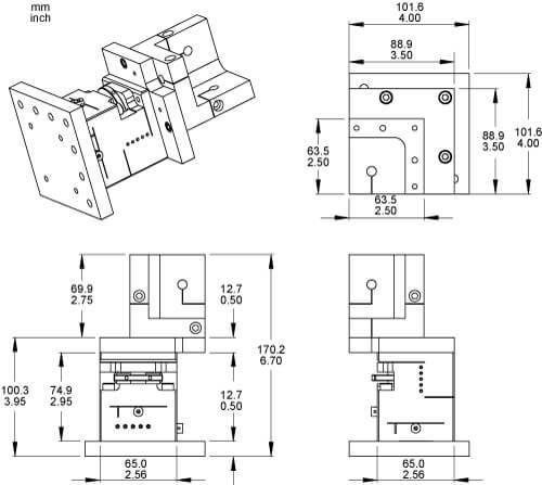
3-Axis Stage
The Standard 3- or 5-Probe nest is mounted to the 3-Axis Stage to allow positioning of the probes when spindle position is fixed. This is primarily used in spindle test stands.
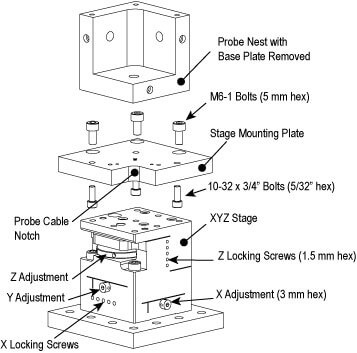
Dimensions