USER’S GUIDE for the
CPA100/CPA100e – Capacitive Displacement Sensor
Approvals and Safety Considerations
The CPA100 is compliant with the following CE directives:
2006/95/EC Low Voltage Directive
2004/108/EC (EMC)
To maintain compliance with these standards, the following operating conditions must be maintained:
- All I/O connecting cables must be less than three meters in length
- AC power cables must be rated at a minimum of 250V and 5A
- AC power must be connected to a grounded mains outlet rated less than 20A
- Use the included CE approved power supply. If an alternative power supply is used, it must have equivalent CE certification and provide safety isolation from the mains according to IEC60950 or 61010.
- Sensors must not be attached to parts operating at hazardous voltages in excess of 30VRMS or 60VDC
- All external connections must be SELV (Safety Extra Low Voltage).
Use of the equipment in any other manner may impair the safety and EMI protections of the equipment.
CPA100 and CPA100e
The CPA100e is identical to the CPA100 except that resolution is limited to a best case of 0.3 μm. For this reason, the CPA100e does not require an export license. This manual will only refer to the CPA100, but all instructions apply to the CPA100e except where noted.
Description
The Lion Precision CPA100 Capacitive Displacement Sensor provides repeatable noncontact measurement of position changes of conductive targets; the CPA100 can also detect nonconductive targets in many applications. The system consists of driver electronics and a probe. The factory calibration information is detailed on a calibration certificate which is shipped with the system.
The CPA100 provides a nonlinear analog voltage proportional to changes in the target position and a digital switched (setpoint) output.
Front Panel Controls and Indicators
 Range Indicator
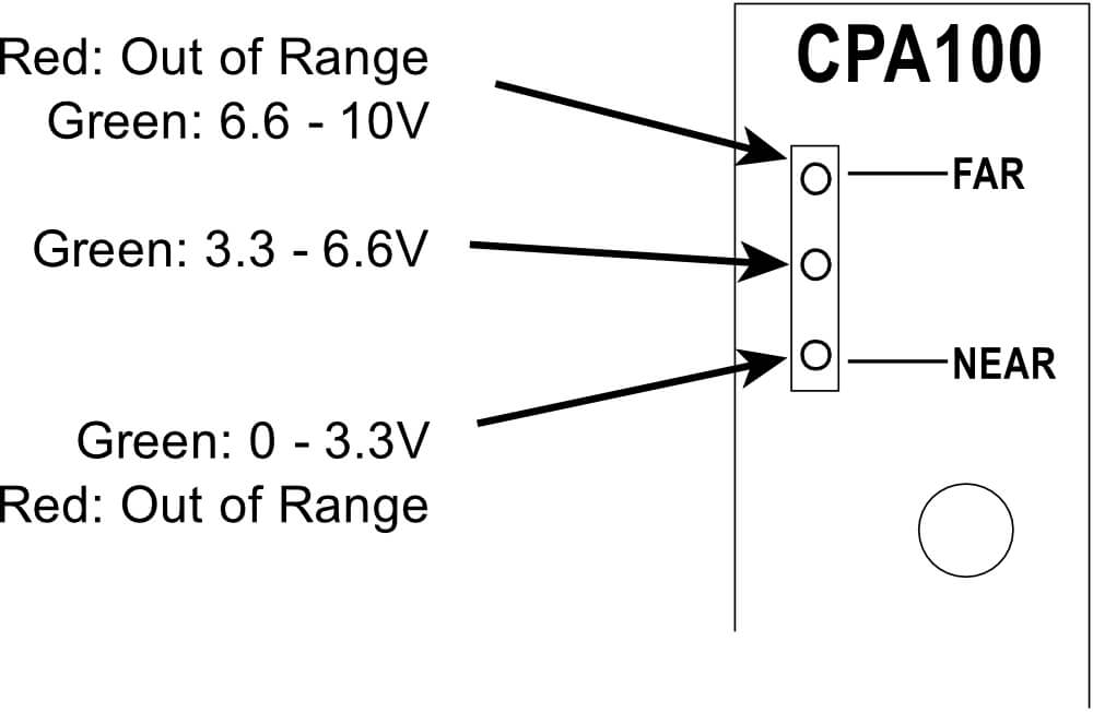
The Range Indicator monitors the output voltage to display out-ofrange conditions and the approximate position of the probe within the 0-10 V range. The NEAR and FAR indicators are red when the output voltage exceeds the 0-10 VDC range; they are green when the output is within 3.3 volts of the end of range. Because the indicator monitors the output voltage, it is affected by the Zero and Gain adjustments.
Zero Adjustment
Turning the Zero Adjustment shifts the DC level of the output voltage. The range of adjustment is ±5 VDC. The adjustment has a 20-turn mechanical range. Over turning will not damage the adjustment. To center the adjustment, turn one direction 20 turns, and reverse direction 10 turns.
Gain Adjustment
Turning the Gain Adjustment changes the sensor’s sensitivity – the amount of output voltage change for a given amount of change in the target position. Adjustment has a range of 0.2 to 5 times the factory calibrated values as listed in the calibration sheet. The adjustment has a 20-turn mechanical range. Over turning will not damage the adjustment. To center the adjustment, turn one direction 20 turns, and reverse direction 10 turns.
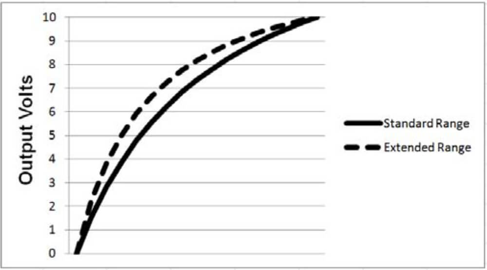
The CPA100 has a nonlinear output; the sensitivity changes throughout the probe range.
Adjusting the gain may affect the Zero Adjustment setting requiring it to be readjusted.
Setpoint Indicator
The CPA100 includes a setpoint output that closes a switch when the output voltage is above or below 5 V, depending on configuration. When the switch is closed this indicator is green. When the switch is open, the indicator is off.
During setup, the Zero Adjustment can be used to set the 5 VDC output to occur at a specific probe/target gap for basic Go/No Go gauging.
Analog Output Signal
The output signal is an analog voltage ranging from 0-10 VDC. The output voltage is proportional to the probe-target gap. As the probetarget gap increases, the voltage becomes more positive.
Turning the Gain Adjustment changes the amount of output voltage change for a change in probe-target gap.
Setpoint Switch Output
When the output voltage rises above 5.5 V, the setpoint switch contacts will close. There is a 0.5 V hysteresis, so the switch remains closed until the output voltage falls below 5.0 V. The setpoint switch polarity can be reversed at the Configuration Jumper Block (see page 7 ).
These contacts have a maximum resistance of 2.5 Ω and can conduct up to 250 mA. The maximum voltage that can be switched is 30VAC/60VDC. The output is a solid state switch closure and can conduct AC or DC.
Using Multiple CPA100s
When multiple CPA100 sensors are used together, the sensors must be synchronized to prevent additional noise in the sensor outputs. Synchronization is accomplished by connecting sync cables between the front panel SYNC connectors (using “T” connectors as required).
Master/Slave Configuration
When two or more sensors are synchronized, one, and only one sensor must be configured as a “master”; all others as “slaves.” If more than two sensors are synchronized, the master should be at the end of the synchronization “chain.”
Sync Termination
If four or more sensors are synchronized, the sensor at the opposite end of the synchronization chain from the master should be set as a “Sync Terminator.” The Sync Terminator ensures that synchronization signals remain undistorted. Only one sensor should be configured as a Sync Terminator. This configuration is accomplished at the Configuration Jumper Block (see page 7).
Probe Excitation Phasing
When using multiple sensors, using different phases of the probe excitation voltage will help improve performance, especially when using an ungrounded or intermittantly grounded target such as a rotating spindle or other moving part. For detailed information on this, see our TechNote LT03-0022 Capacitive Sensors and Ungrounded Targets. The TechNote is available in the Technical Library on our web site (www.lionprecision.com)
The probe drive voltage can be selected as Phase 1 or Phase 2. This is accomplished at the Configuration Jumper Block (see page 7 ).
Remote Control of Zero and Gain
Zero and Gain adjustments can be made with remote potentiometers connected to the CPA100. A separate connector is provided for each control and requires connection of the Clockwise, Counter-Clockwise, and Wiper contacts from the external potentiometer. The Zero adjustment requires a 10 kΩ potentiometer, and the Gain adjustment requires a 50 kΩ potentiometer.
Remote adjustments will function identically to front panel adjustments. Because these are connected directly into sensitive parts of the circuit, connections should be kept as short as possible and shielded wiring is recommended.
Using remote potentiometers for these adjustments requires changes to the Configuration Jumper Block. See Configuration Jumper Block section for details (page 7).
Connecting to the CPA100
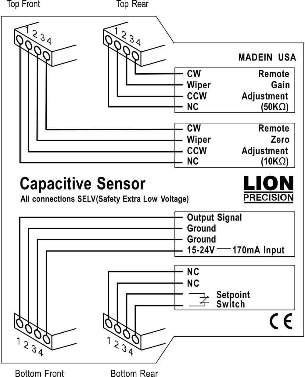
| Connections | Description | Notes | |
| Pin | Bottom-Front Connector: Power and Analog Output | ||
| 1 | Output Signal | Output Signal Voltage | 0-10VDC |
| 2 | Ground | Ground | |
| 3 | Ground | Ground | |
| 4 | 15-24VDC | Input Power, 15-24VDC from CE approved power source | 170mA max. |
| Top-Rear Connector: Remote Gain Adjustment 50 kΩ Potentiometer | |||
| 1 | CW | Potentiometer clockwise terminal | Shielded cable recommended |
| 2 | Wiper | Potentiometer wiper terminal | |
| 3 | CCW | Potentiometer counter-clockwise terminal | |
| 4 | NC | No Connections | |
| Top-Front Connector: Remote Zero Adjustment 10 kΩ Potentiometer | |||
| 1 | CW | Potentiometer clockwise terminal | Shielded cable recommended |
| 2 | Wiper | Potentiometer wiper terminal | |
| 3 | CCW | Potentiometer counter-clockwise terminal | |
| 4 | NC | No Connections | |
| Bottom-Rear Connector: Setpoint Switched Output | |||
| 1 | NC | No Connection | |
| 2 | NC | No Connections | |
| 3 | Switch | Contact 1 of switched output |
3VAC, 60VDC 250mA max |
| 4 | Switch | Contact 2 of switched output | |
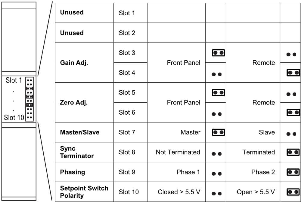
Configuration Jumper Block
The configuration jumper block is located on the rear of the CPA100 in the area of the DIN rail mount. This block contains jumpers to configure various aspects of the device. The table below provides details.
Jumper On![]()
Jumper Off![]()
Specifications
| Parameter | Specification | Notes |
| Power Requirement | 15-24 VDC, 2.5 W | Use CE compliant source |
| Resolution (Typical)1,2 |
0.03% (CPA100) 0.3 μm or higher (CPA100e) |
@15 kHz |
| Bandwidth | 15 kHz (-10%/+30%) | |
| Analog Output1 |
0-10 VDC calibrated range, -0.8-12 VDC full range, 0 Ω |
|
| Setpoint Switch Output |
Solid state switch closure: 30 VAC/60 VDC max 2.5 Ω, 100mA max Offstate leakage: < 1 nA |
|
| Driver and Prober Operating Environment | 4°C to 50°C |
1Actual values depend on probe and range and are listed on the calibration certificate shipped with the product. Contact Lion Precision for replacement certificates.
2In High EMI environments (10 V/m), output noise levels may rise to 0.25 Vrms
Typical Output Linearity
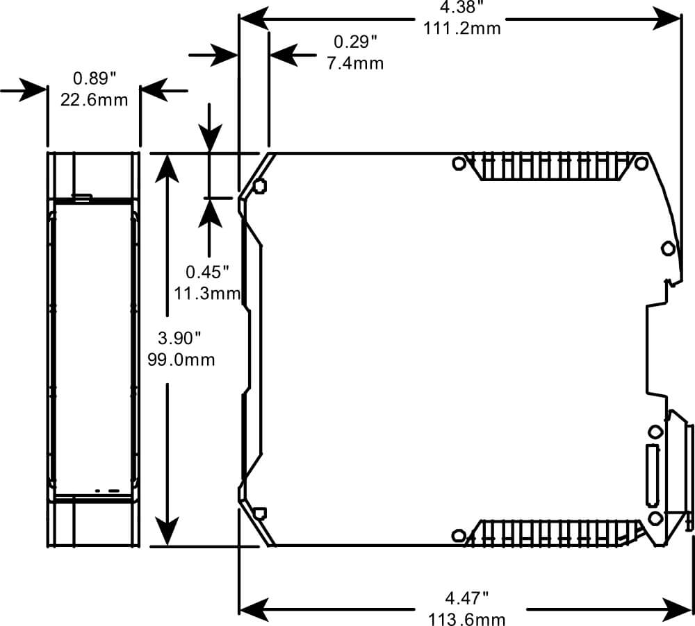
Mechanical Detail