General Sensor Application Note LA05-0060
Copyright © 2013 Lion Precision. www.lionprecision.com
Summary:
Virtually all capacitive and eddy-current sensor applications are fundamentally a measure of displacement (position change) of an object. This Application Note details the specifics of making such a measurement and what is required to make reliable measurements in micro and nano displacement applications.
Capacitive sensors work in clean environments and provide highest precision. Eddy-Current sensors can work in wet, dirty environments. They provide an economical replacement for laser interferometers when the probes can be mounted near the object and total displacements are small.
Linear Displacement and Position Measurement With A Noncontact Linear Displacement Sensor
Linear displacement measurement here refers to the measurement of the position change of an object. Linear high-resolution non-contact displacement measurement of conductive objects with capacitive sensors and eddy-current sensors is specifically the topic of this Application Note. Capacitive sensors can also measure non-conductive objects. A discussion of measuring non-conductive objects with capacitive displacement sensors can be found in our Capacitive Sensor Theory of Operation TechNote (LT03-0020).
Related Terms and Concepts
Because of the high-resolution, short-range nature of capacitive displacement sensors and eddy-current displacement sensors, this is sometimes referred to as micro-displacement measurement and the sensors as a micro-displacement sensor or micro-displacement transducer. A sensor configured for a linear displacement measurement is sometimes called a displacement meter or displacement gauge.
Displacement Versus Absolute Position
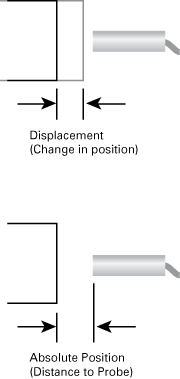
At the micro and nano level, capacitive and eddy-current displacement sensors are best suited to displacement measurements (change in position) , rather than absolute position measurements.
Displacement is a measurement of the position change of an object. Absolute Position is a measurement of the precise distance between the sensor’s measurement surface and the object.
Capacitive and Eddy-Current sensors are primarily used as displacement sensors. Over time (months and years), sensor calibration shifts slightly. This shift is primarily a DC offset in the output of the sensor. There is also a slight DC shift relative to temperature. This DC offset will cause a small error in absolute position measurement that increases over time. These errors are small, but at the sub-micron level, the can affect precision.
Changes in Sensitivity (gain) of the sensor are much smaller. Measuring real-time changes in position requires a consistent Sensitivity and is not affected by long-term shifts in DC offset of the output. For this reason, capacitive and eddy-current displacement sensors are usually used to measure relative position (displacement), not absolute position, especially for micro-displacements in which there is a need for resolution at the sub-micron or nanometer level.
Displacement is usually measured as a result of some variable.
The typical reason for measuring displacement, especially micro displacement, is to determine how an object responds to some changing condition. Displacement measurement is usually answering the question: How far does this move when something else changes?
Intentional Displacement: The object is intentionally moved by a motion control positioning system. The non-contact displacement measurement indicates the accuracy of the intended displacement of the object.
Part Dimension: The system is configured with a known good “master” part after which the master part is replaced with a part for test. Differences in the dimensions of the test part relative to the master part are indicated as a displacement measurement by the sensors.
Temperature: The object’s position is measured at an initial temperature. The temperature of interest is changed (often occurring naturally as a machine operates) and a displacement measurement indicates the magnitude of the position change due to temperature.
Vibration: Linear displacement measurements are made in real time using capacitive or eddy-current displacement sensors with an oscilloscope or data acquisition system to indicate the displacements of the object and their frequencies. See our Vibration Measurement Application Note for more detail.
Pressure: Air bearings and other fluid bearings can operate at different fluid pressures. Displacement measurements of the object at different pressures indicate the actual behavior of the machine as the pressure changes compared to its intended operation.
Wear: As bearings and slides wear, non-contact displacement measurements of the moving parts will indicate increased movement in unintended directions. Rotary motions will show increasing displacements in the X, Y, and Z axes as the object turns. Linear slides will show increasing displacements in the two axes perpendicular to the direction of travel.
Linear Displacement Measurements are Relative Measurements
Linear non-contact displacement measurements are relative measurements and indicate the change of an object’s position from an initial location in one or more linear axes. A separate displacement or position sensor channel is required for each axis of linear displacement measurement.
Basic Linear Displacement Measurement with a Capacitive and Eddy-current Displacement Sensors
The displacement sensor is mounted in a fixture such that the object to be measured is within the measurement range of the sensor. If the sensor includes a zero (offset) adjustment, the sensor may be zeroed at this location to make for easier interpretations of linear displacement measurements when the object moves. If zero adjustment if not possible, the initial output of the displacement sensor is recorded and that value is subtracted from future measurements to indicate the change in position from the initial position.
Calculating Displacement from Displacement Sensor Output
Sensors for measuring displacement have a “sensitivity” specification which specifies the amount of change in the output relative to a given change in the target position. For analog voltage output sensors, this value is given in Volts per unit-of-distance or length (e.g. mm, inch etc.). For digital output sensors, this value is given in Counts per unit-of-distance. When measuring displacement, this sensitivity is used to calculate the physical displacement relative to the change in output.
Formula for calculating displacement from a sensor output:
Displacement = Output Change / Sensitivity
Analog Voltage Output sensors:
Output Change in Volts; Sensitivity = Volts/Unit of distance
Digital Output sensors:
Output Change in Counts; Sensitivity = Counts/Unit of distance
Micro-displacement Errors and Concerns
High-Performance capacitive displacement sensors and eddy-current displacement sensors are usually used to measure micro-displacements. When measuring displacements at the micro-displacement level, error sources that are normally inconsequential become a more significant factor.
Thermal Effects on Mounting
Thermal expansion and contraction of the mounting system that holds the non-contact displacement sensors or the target object will introduce errors into the measurement. As the fixture expands or contracts, the sensor may move toward or away from the target object. The displacement is real and will affect the measurement, but it is not a displacement caused by whatever conditions are being tested for. Linear displacement sensor mounting systems must be robust, stiff, and as thermally stable as possible. In ultra-precise applications the environment is tightly controlled and/or mounting systems are built from invar or other zero-expansion materials.
Micro-displacement Sensor Mounting
In addition to thermal concerns, mechanical stability is more complicated at the micro level. The displacement measurement sensors must be held firmly in place by the mounting system. A simple set-screw type mount may not be sufficiently stable when measuring displacement at the micro or nano level.
There are different methods for mounting a smooth, cylindrical linear displacement sensor. Using a set-screw in a thru-hole mount only holds the probe at two points – the set-screw and the point opposite the set-screw. The probe is free to rotate in the axis 90° from the set-screw axis. Depending on the width of the surface against which the set-screw pushes the probe, the probe may also be able to rotate along its axis as well. Increasing the force on the set-screw will not increase the probe’s stability in these other two axes.
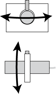
Set-screw mounting locks the probe along the probe’s axis, but there may still be movement in the other two axes, especially at the micro and nano levels.
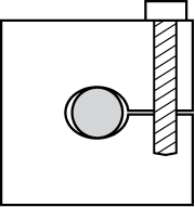
A clamp mount is a more stable mount than a set-screw mount. But at the micro and nano levels, form errors can result in only a two-point clamp much like a set-screw mount.
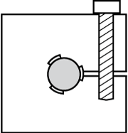
A three-point clamp mount is inherently stable and not effected by small form errors in roundness.
A better, but not perfect linear displacement sensor mounting scheme is a clamp type mount. This mounting system can stabilize the probe in all three axes if the mounting hole and probe are perfectly round. However, any eccentricity of either part will result in a two-point mounting system similar to the set-screw system.
An optimal mounting system uses a multiple-point clamp with each point covering some significant length along the axis of the probe. The clamp system begins with a typical clamp mounting configuration but also removes material from the clamping hole between three or four points around the circumference of the mounting hole. This arrangement is not affected by eccentricity of the mounting hole or the eccentricity of the non-contact linear displacement measurement sensor – it is stable in all three axes.
Other Considerations Unique to Capacitive Displacement Sensors
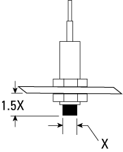 The “spot-size” of capacitive displacement sensors is about 130% of the sensing area diameter. For this reason, they are generally immune to any surrounding objects, and they can be mounted flush with the mounting bracket surface. The only exception is calibrations that use an extremely long measurement range relative to the size of the sensing area; this does not apply to any off-the-shelf calibrations available for Lion Precision probes.
Environmental Considerations
Linear displacement measurements with capacitive sensor must be made in a clean environment. The displacement measurement will be affected by anything (other than air or vacuum) in the space between the capacitive probe and the object it is measuring.
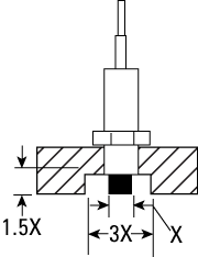
Eddy-current probe mounting must allow a metal-free space around the tip at least three times the probe diameter. Flush mounting requires a counter bore.
Capacitive sensors have some sensitivity to temperature, but the systems are compensated for temperature changes between 20°C and 35°C with a drift of less than 0.04%F.S./°C.
Typical changes in humidity do not have a significant effect on capacitive displacement measurements. Extremes of humidity will affect the output with a worst case being condensation on the probe or target.
Other Considerations Unique to Eddy-Current Displacement Sensors
Eddy-Current displacement sensors use a magnetic field that engulfs the end of the probe. As a result, the “spot-size” of eddy-current displacement sensors is about 300% of the probe diameter. This means any metallic objects within three probe diameters from the probe will affect the sensor output.
This magnetic field also extends along the probe’s axis toward the rear of the probe. For this reason, the distance between the sensing face of the probe and the mounting system must be at least 1.5 times the probe diameter. Eddy-Current displacement sensors cannot be mounted flush with the mounting surface.
If interfering objects near the probe is unavoidable, a special calibration, ideally done with the probe in the fixture, will have to be performed.
Multiple Probes
When multiple probes are used with the same target, they must be separated by at least three probe diameters to prevent interference between channels. If this is unavoidable, special factory calibrations are possible to minimize interference.
Environmental Considerations
Linear displacement measurements with eddy-current sensors are immune to foreign material in the measurement area. The great advantage of eddy-current non-contact sensors is that they can be used in rather hostile environments. All non-conductive materials are invisible to eddy-current sensors. Even metallic materials like chips from a machining process are too small to interact significantly with the sensors.
Eddy-Current sensors have some sensitivity to temperature, but the systems are compensated for temperature changes between 15°C and 65°C with a drift of less than 0.01%F.S./°C.
Changes in humidity have no effect on eddy-current displacement measurements.
