USER’S GUIDE for the
CPL350 – Capacitive Displacement Sensor
Table of Contents
- APPROVALS AND SAFETY CONSIDERATIONS
- OVERVIEW
- CONNECTING TO THE CPL350
- CHANGING THE BANDWIDTH
- SPECIFICATIONS
- MECHANICAL DATA
- OPTIONAL MOUNTING FLANGE
Approvals and Safety Considerations
The CPL350 is compliant with the following CE standards:
Safety: EN 61010-1:2010
EMC: IEC 61326-1:2013, IEC 61326-2-3:2013
To maintain compliance with these standards, the following operating conditions must be maintained:
- All I/O connecting cables must be shielded and less than three meters in length
- Use the included CE approved power supply. If an alternative power supply is used, it must have equivalent CE certification and provide safety isolation from the mains according to IEC60950 or 61010.
- Sensors must not be attached to parts operating at hazardous voltages in excess of 33VRMS or 70VDC
Use of the equipment in any other manner may impair its safety and EMI protections.
Overview
The CPL350 Capacitive Displacement Sensor provides one channel of noncontact displacement measurement for precision position and displacement applications. This manual will provide you with all the information you require to get the greatest benefit from your system.
Engineers, technicians, and maintenance personnel will find the CPL350 invaluable for high-precision measurements of mechanical displacement where contact with the target is not possible nor advisable. Targets such as high-speed rotating spindles, or parts that could be damaged or deflected by contacting probes can be measured with confidence and accuracy.
System Contents
Your system includes this manual, the CPL350 Capacitive Sensor electronics, power supply, one probe, and a NIST traceable calibration sheet.
Calibration
Your system was calibrated with a precision calibrator designed by Lion Precision. The system is calibrated with nanometer precision. All of our calibrations are traceable to NIST.
Lion Precision recommends that you have your system recalibrated at the factory once a year to ensure maximum accuracy.
Using this Manual
In this manual you will find information for connecting and using your CPL350. Once you become familiar with the system, you will only need to refer occasionally to this manual for specifications or to verify connection information.
Getting Help
Lion Precision wants to help you get the most from your system. If there is anything we can do, contact us:
Telephone: 800-292-6544, 651-484-6544
General information: info@lionprecision.com
Service or calibration: support@lionprecision.com
Sales: sales@lionprecision.com
Technical Library
Our website includes a Technical Library filled with useful information on making the most precise measurements possible, as well as product information and manuals: www.lionprecision.com, click the Technical Library menu item.
Connecting to the CPL350
Probe Connections
- Insert the probe cable connector into the “Probe” connector on the CPL350.
- Rotate until the red dots on the connectors align.
- Push the connector in until it clicks.
- Pull on the knurled barrel of the probe connector which will release the latching mechanism.
The probe cannot be disconnected by pulling on the cable.
Analog Output BNC Connector
Analog output is ±10 V. The output voltage becomes more positive as the probe gets closer to the target. The scaling of the output (i.e. V/mm) is dependent on the probe and calibration specified when ordered. The complete calibration information is available on the NIST traceable calibration sheet provided with the sensor.
Power & Differential Analog Output Connector
9-Pin, Male, D-Sub connector with 4-40 mounting hardware.
Pin Assignments
| Pin | Connection |
| 1 | Ground |
| 2 | N/C |
| 3 | -15VDC |
| 4 | +15VDC |
| 5 | N/C |
| 6 | Non-Inverted Analog Output |
| 7 | Inverted Analog Output |
| 8 | Ground |
| 9 | Ground |
Power Supply Requirements
The power supply provided with your CPL350 provides the required ±15VDC input power. If using your own power supply, be aware that high-frequency noise from a switching-type power supply may appear in the output. For high resolution results, be sure to provide clean power.
Differential Outputs
The Non-Inverted and Inverted outputs are used together as a differential output. Differential outputs help eliminate electrical noise induced into the connecting wires by noise sources such as computers, power transformers etc.
The Non-Inverted output voltage becomes more positive (relative to ground) as the probe nears the target. The Inverted output voltage becomes more negative (relative to ground) as the probe nears the target. The Non-Inverted and Inverted outputs are each ±5 VDC relative to ground; the differential output is therefore ±10 VDC.
Do NOT connect the outputs to ground or the unit will be damaged.
Differential Outputs as Single-Ended
The Non-Inverted or Inverted outputs can be used as a ground referenced single ended output, but the sensitivity will be half of that indicated on the calibration sheet. For instance, a differential output calibrated for 1 V/mm will produce 0.5 V/mm when used as a single-ended output.
Signal Ground Connection
A ground connection screw is provided for an optional ground connection to data acquisition devices. Connecting the CPL350 ground and data acquisition ground may improve performance. Consult your data acquisition manual for more details.
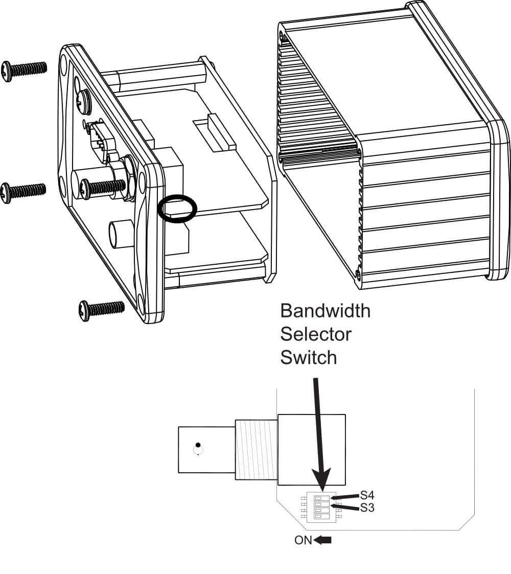
Changing the Bandwidth
Higher bandwidths allow you to accurately measure faster moving targets.
Lower bandwidth reduces the noise on the output and creates higher resolution.
The CPL350 is set to 15 kHz unless specified otherwise in the order and on the calibration sheet received with the system.
Two switches inside the enclosure set the bandwidth. To change them:
- Remove the 4 screws that attach the front panel to the cover.
- Bandwidth is controlled by positions 3 and 4 of DIP-switch S1.
DO NOT CHANGE ANY OTHER SWITCHES
Set the desired bandwidth according to the this table:
| S3 | S4 | Bandwidth |
| ON | ON | 100 Hz |
| ON | OFF | 1 kHz |
| OFF | ON | 10 kHz |
| OFF | OFF | 15 kHz |
Specifications
| Resolution* | 0.004%F.S. at 15 kHz typical, dependent on calibration |
| Linearity Error | ±0.5% F. S. typical, dependent on calibration |
| Error Band | ±1.0% F. S. typical, dependent on calibration |
| Bandwidth (-3 db) |
DIP Switch selectable 100 Hz, 1 kHz, 10 kHz, 15 kHz ( –10%+30%) |
| Operating Temperature | 4°-50°C |
| Probe Thermal Stability | 0.04% F.S./°C |
| Output Impedance | 0Ω |
| Output Voltage Max | ±13.5 VDC |
| Output Max Current | 20 mA |
| Power Input |
+15 VDC (±5%) @ 95 mA max –15 VDC (±5%) @ 95 mA max |
*RMS; Peak-to-peak value are typically 8-10 times greater than the RMS values. In high EMI conditions (10 V/m), output DC level may shift and noise may rise to 0.25 VRMS (1.3% resolution)
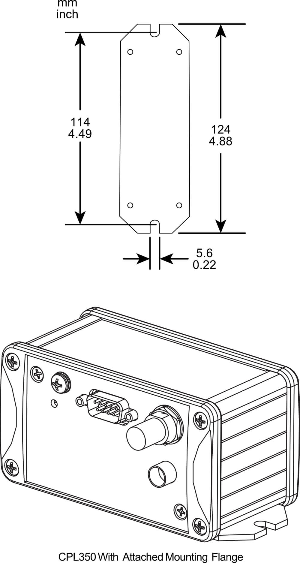
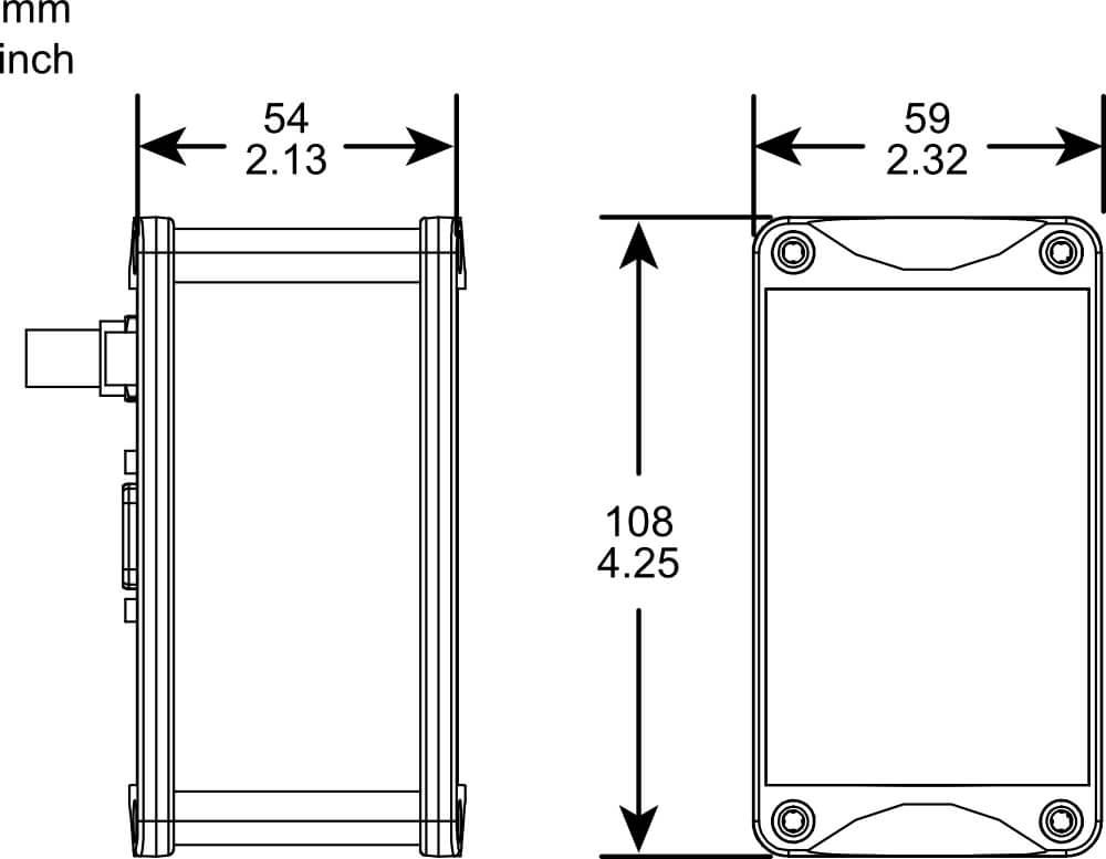
Mechanical Data
Optional Mounting Flange
An optional flange for easy mounting of the CPL350 is available (P017-6455). The flange attaches to the bottom of the device with four flathead screws (included in the flange kit).